


140-072011 200/202 Series Page 8 of 24
2. Installation and Operation
This section contains the steps necessary to install a new flow meter/controller into operation as quickly
and easily as possible. Please read the following thoroughly before attempting to install the instrument.
2.1. Receiving Inspection
Carefully unpack the Hastings HFM-200/HFC-202 series instrument and any accessories that have also
been ordered. Inspect for any obvious signs of damage to the shipment. Immediately advise the carrier
who delivered the shipment if any damage is suspected. Check each component shipped with the packing
list. Insure that all parts are present (i.e., Flowmeter, power supply, cables, etc.). Optional equipment or
accessories will be listed separately on the packing list. There may also be one or more OPT-options on
the packing list. These normally refer to special ranges or special gas calibrations. They may also refer to
special helium leak tests, or high pressure tests. In most cases, these are not separate parts, but special
options or modifications built into the flow meter.
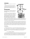
2.2. Power Requirements
The HFM-200/HFC-202 series (bipolar 15 Volt version) require ±15 VDC @ ±30 mA / 1 Watt
(HFM-200) +60 mA, -185 mA / 3 Watts (HFC-202) for proper operation. The supply voltage should
be sufficiently regulated to no more than 50 mV ripple. The supply voltage can vary from 14.0 to 16.0
VDC. Surge suppressors are recommended to prevent power spikes reaching the instrument. The
Hastings power supplies described in Section 1.4.1 satisfy these power requirements.
The HFM-200/HFC-202 series (24 Volt version) require 14 - 32 VDC @ 1.9 Watts (HFM-200) and
4.2 Watts (HFC-202) for proper operation. The supply voltage should be reasonably regulated as power
supply ripple may propagate to the output. The supply common is galvanically isolated from the signal
common such that this instrument can be powered from a bipolar 15 Volt supply using only the positive
and negative output terminal (30 Volts). Surge suppressors are recommended to prevent power spikes
reaching the instrument.
The HFM-200/HFC-202 series instruments have an integral 5 VDC reference source. This stable
voltage is on pin 15 of the DA-15 connector (pin 1 of the DE-9 for 24 Volt) and may be used for the
command voltage.
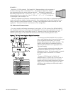
2.3. Output Signal
The standard output of the flow meter is a 0-5 VDC signal proportional to the flow rate. In the
Hastings power supplies, the output is routed to the display and is also available at the terminals on the
rear panel. If a Hastings supply is not used, the output is available on pin 6 of the DA-15 connector (pin
2 of the DE-9 for 24 Volt) and is referenced to pin 5 (pin 8 for 24 Volt). It is recommended that the load
resistance be no less that 2kΩ. If the optional 4-20 mA output is used, the load impedance must be
selected in accordance with Section 1.3.
Attempting to operate the 24 volt version for any significant length of time
the internal DC- DC convertors to fail.
Warning:
at a voltage less than the specified minimimum voltage will cause