


140-072011 200/202 Series Page 3 of 24
Table of Contents
1.
GENERAL INFORMATION....................................................................................................................................4
1.1. FEATURES............................................................................................................................................................4
1.2. SPECIFICATIONS HFM-200
*
.................................................................................................................................5
1.3. SPECIFICATIONS HFC-202
*
..................................................................................................................................5
1.4. OPTIONAL 4-20 MA CURRENT OUTPUT ...............................................................................................................6
1.5. OTHER ACCESSORIES...........................................................................................................................................6
1.5.1. Hastings Power supplies.................................................................................................................................6
1.5.2. Interconnecting Cables...................................................................................................................................7
2. INSTALLATION AND OPERATION.....................................................................................................................8
2.1. RECEIVING INSPECTION .......................................................................................................................................8
2.2. POWER REQUIREMENTS .......................................................................................................................................8
2.3. OUTPUT SIGNAL...................................................................................................................................................8
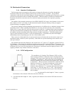
2.4. MECHANICAL CONNECTIONS...............................................................................................................................9
2.4.1. Standard Configuration ..................................................................................................................................9
2.4.2. LFE Configuration .........................................................................................................................................9
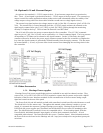
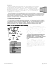
2.5. ELECTRICAL CONNECTIONS...............................................................................................................................10
2.6. OPERATION........................................................................................................................................................11
2.6.1. Operating Conditions ...................................................................................................................................11
2.6.2. Zero Check...................................................................................................................................................12
2.6.3. High Pressure Operation ..............................................................................................................................12
2.6.4. Blending of Gases ........................................................................................................................................12
2.7. OPERATION WITH EXTERNAL DEVICES..............................................................................................................12
2.7.1. Operation with a Hastings power supply......................................................................................................12
2.7.2. Operation with a Power Supply other than a Hastings .................................................................................13
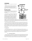
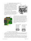
2.7.3. Operation with an external sensor (Fig. 2.2) ...............................................................................................14
2.7.4. Response to Command Changes ..................................................................................................................14
2.8. RANGE CHANGING.............................................................................................................................................15
2.9. VALVE-OVERRIDE CONTROL.............................................................................................................................15
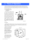
3. THEORY OF OPERATION ...................................................................................................................................16
3.1. OVERALL FUNCTIONAL DESCRIPTION................................................................................................................16
3.2. SENSOR..............................................................................................................................................................16
3.3. ELECTRONICS ....................................................................................................................................................17
3.4. SHUNT ...............................................................................................................................................................17
3.5. VALVE ...............................................................................................................................................................18
4. MAINTENANCE......................................................................................................................................................19
4.1. AUTHORIZED MAINTENANCE.............................................................................................................................19
4.2. TROUBLESHOOTING ...........................................................................................................................................19
4.3. ADJUSTMENTS ..............................................................................................................................................20
4.3.1. Calibration Procedure: (Figure 4.1)..............................................................................................................20
4.3.2. Miscellaneous adjustments...........................................................................................................................21
4.4. END CAP REMOVAL...........................................................................................................................................21
4.5. PRINTED CIRCUIT BOARD REPLACEMENT..........................................................................................................21
4.6. SENSOR REPLACEMENT .....................................................................................................................................21
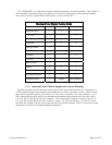
4.7. ORIFICE CHANGES .............................................................................................................................................21
4.7.1. HFC-202 Orifice ..........................................................................................................................................22
5. WARRANTY AND REPAIR ..................................................................................................................................24
5.1. WARRANTY REPAIR POLICY..............................................................................................................................24
5.2. NON-WARRANTY REPAIR POLICY .....................................................................................................................24