


140-072011 200/202 Series Page 19 of 24
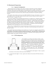
4. Maintenance
This section contains service and calibration information. Some portions of the instrument are delicate.
Use extreme care when servicing the flow controller.
4.1. Authorized Maintenance
With proper care in installation and use, the flow controller will require little or no maintenance. If
maintenance does become necessary, most of the instrument can be cleaned or repaired in the field.
Some procedures may require recalibration. Do not attempt these procedures unless facilities are
available. Entry into the sensor or tampering with the printed circuit board will void the warranty. Do
not perform repairs on these assemblies while unit is still under warranty.
4.2. Troubleshooting
SYMPTOM: Override CLOSE function is enabled but flow remains or 0.00 VDC is commanded and
flow remains.
CAUSE: Orifice out of adjustment or faulty op-amp
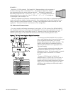
ACTION: Check the valve voltage between pins 2 & 12 on the 15-pin D-connector for 15 Volt units and
Pins 5 & 8 on the DE-9 connector for 24 Volts. If the voltage is less than 3.00 VDC, then turn the orifice
clockwise until flow stops.
SYMPTOM: Output of unit is proportional to flow but extremely small and not correctable by span pot.
CAUSE: Sensor is not being heated.
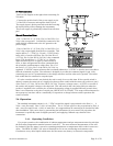
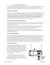
ACTION: Unplug connector J1. Check the following resistance: The resistance between pins 2 & 3 of
the sensor should be approximately 2500 Ohms (see Figure 3.1 on page 8). The resistance between pins
1 & 4 should be approximately 2.3 Ohms. The resistance between pins 2 & 3 and the base of the sensor
should be essentially infinite. If not, replace the sensor unit. If sensor reads O.K., check the voltage
output on pins 2 & 3 of the jack in the board. If it does not read approximately 22 VDC then replace
regulator U2 (U3 on 24 Volt board).
SYMPTOM: Sensor has proper resistance readings, but little or no output with flow.
CAUSE: Plugged sensor.
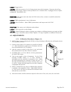
ACTION: Shut off gas supply and power supply. Remove cover and PC board from unit. Remove
sensor assembly and examine. If sensor has evidence of plugging, clean or replace as applicable
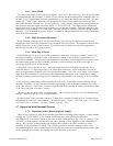
SYMPTOM: Flow controller oscillates.
CAUSE: Flow controller not adjusted for the dynamics of the flow system.
ACTION: Check upstream and downstream pressures. The gas supply regulator should not have
excessive lockup when flow shuts off. Also ensure that there is not a large drop in pressure between the
regulator and the instrument due to line resistance. Oscillations can also be caused if a large flow
restriction is pneumatically close to the downstream end of the flow controller. The differential pressure
across the unit must be between 10-50 psig.
SYMPTOM: Little or no flow, even with Valve Override OPEN enabled.