


140-072011 200/202 Series Page 21 of 24
4.3.2. Miscellaneous adjustments
Periodically, during normal operation, the ZERO should be checked and adjusted when required. If the
instrument is not shutting completely off when the Valve Override CLOSE function is active, or a
command of zero flow has been given, then the orifice may require approximately 1/8 turn clockwise.
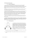
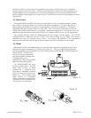
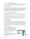
4.4. End Cap Removal
The end cap on the inlet side must be removed to gain access to the filter or shunt assembly. First shut
off the supply of gas to the instrument. Disconnect the Swagelok fitting on the inlet and outlet sides of
the transducer, and remove it from the system plumbing. Remove the four hex bolts holding the end cap
to the instrument (see Figure 4.1). Carefully remove the end cap, filter, wave spring (if present) and
shunt, noting their order and proper orientation. The shunt can be severely damaged if dropped.
Examine the filter and shunt. If either is dirty or blocked, clean or replace as applicable. Reassembly is
the reverse of the removal procedure. Recalibration of the HFC is necessary.
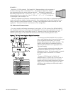
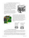
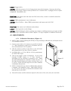
4.5. Printed Circuit Board Replacement
In the unlikely event that the PC board fails, it is easily removed from the instrument and replaced with
a spare to minimize instrument downtime. Replacement of the PC board will require the instrument to
be recalibrated per Section 4.3.1.
Unplug the power cable from the top of the transducer. Remove the two jackscrews next to the “D”
connector and the two screws on the sides of the cover. Lift off the cover and unplug the four-wire
sensor plug and the two wire valve plug, noting their orientation prior to removal.
Remove the screw that holds the PC board to the sensor. Troubleshoot or replace as applicable.
Installation is the reverse of the above procedure. Recalibrate if any components were changed or if any
potentiometers were adjusted.
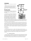
4.6. Sensor Replacement
If the sensor fails or becomes plugged it can be removed. Remove the cover and the PC board per
Section 4.5 above. Remove the three bolts holding the sensor to the instrument base. Remove the sensor
from the base noting the two O-rings (Parker 2-005, V884-75) between the sensor and the base. If the
sensor is plugged it can be cleaned by running a fine wire (approximately 0.008" diameter) through the
tube. If sensor needs replacement, obtain another from the factory and install it. Ensure that O-rings are
clean and intact. Install O-rings on seating surface, then carefully place sensor over O-rings and tighten
down the three screws evenly. Replacement of sensor will require recalibration per Section 4.3.1.
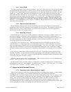
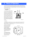
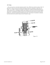
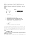
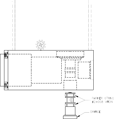
4.7. Orifice Changes
The orifice may require replacement if a large flow
range change is desired, if changing to a gas that has a
specific gravity significantly different than the original
gas, if a large change in the differential pressures across
the valve is desired or in the event that a small orifice
becomes plugged. Replacement orifices can be acquired
from the factory. The diameter of the orifice can be
calculated using the following procedure:
Orifice Changes:
A) Determine the minimum expected upstream
pressure (P
u
) in absolute pressure units (add
atmospheric pressure – 14.7 psia) and the maximum
expected downstream pressure (Pd) in absolute pressure
units for full flow conditions.