


Page 9
REMOTE VEHICLE STARTER INSTALLATION MANUAL
Step 1 - Connect All Of the Following Wires
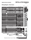
6 Pin Power Connector
Yellow 30amp Starter Output 12volts during start position only.
Green 30amp Heater Output 12volts in the accessory position off during start
and 12volts during run.
Red 30amp Power Input Constant 12volt power at ignition harness or from the battery.
Red 30amp Power Input Constant 12volt power at ignition harness or from the battery.
Blue 30amp Ignition Output 12volts in the ignition, start and when run positions.
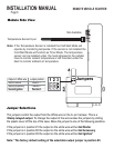
White 30amp Select Output* Selectable Output for vehicles that require 2nd
Ign, Acc or Starter wires. See jumper diagram.
* The white wire may not be required on all vehicles.
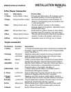
14 Pin
Connectors
Black System Ground Input Connect to Chassis Ground.
White Park Light Output Connect to (+) Park Light system.
Green/Wht Hood Pin Input Connect to the Hood Pin Safety Switch.
Blue/White Tach Connect To A/C Tach Source. (Above 2volts AC)
Pink Brake Switch Connect To (+) When Brakes Is Applied.
Manual Transmission Connections (”M” Models Only)
Black/Wht Park Brake Input - Connect to Park Brake wire.
Green* (-) Door Pin Input - Connect to door pin (-) when doors opened.
Purple* (+) Door Pin Input - Connect to door pin (+) when doors opened.
Note: Connect only one of the door pin inputs. If the vehicle has a positive door pin system
connect the purple wire, if negative connect the green wire.
Never install an automatic module into a manual transmission vehicle!
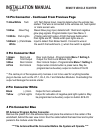
Step 2- Plug-In The Module
When all the connections are done, the control module can be plugged in. Before
connecting the control module, make sure the ignition is in the OFF position. Plug in the
6 pin harness and the Auxiliary harness, then any other connectors that were used. The
park lights will flash and the horn will honk 2 times to confirm power up on automatic
transmission models. Manual transmission models will flash the park lights and honk
the horn 4 times to confirm power up.