


AL35 User Manual ◄ 3
SERVICING: This manual contains safety, operation, and routine maintenance instructions. Stanley Hydraulic Tools
recommends that servicing of hydraulic tools, other than routine maintenance, must be performed by an authorized
and certied dealer. Please read the following warning.
For the nearest authorized and certied dealer, call Stanley Hydraulic Tools at the number listed on the back of this
manual and ask for a Customer Service Representative.
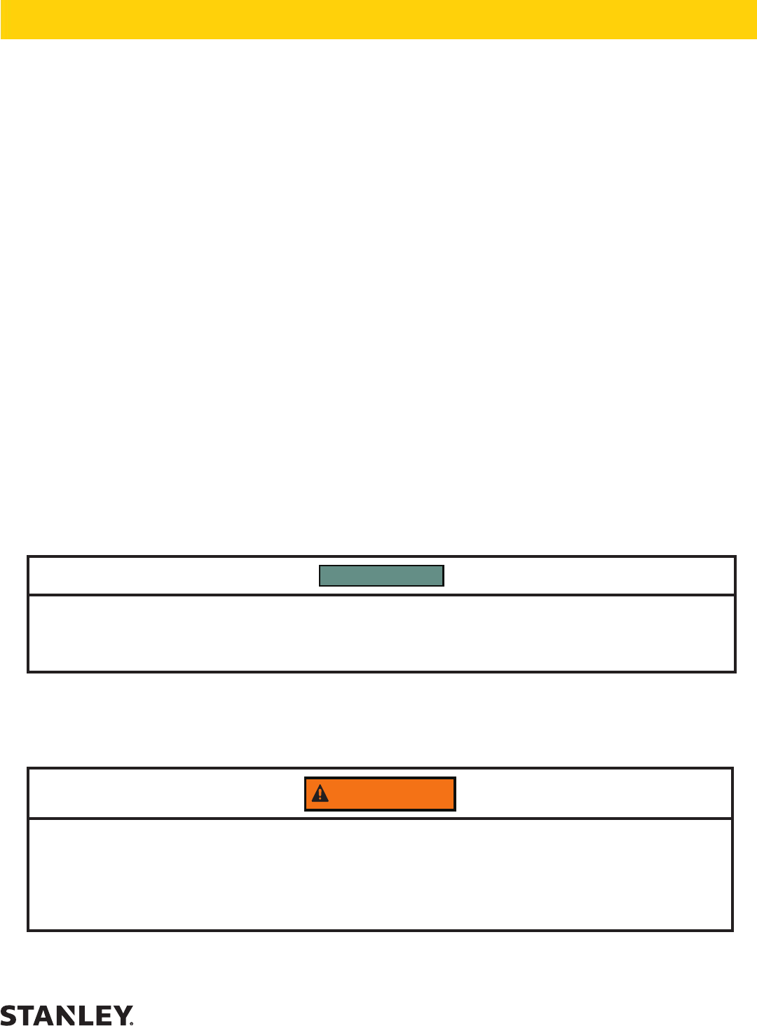
WARNING
SERIOUS INJURY OR DEATH COULD RESULT FROM THE IMPROPER REPAIR OR
SERVICE OF THIS TOOL.
REPAIRS AND / OR SERVICE TO THIS TOOL MUST ONLY BE DONE BY AN
AUTHORIZED AND CERTIFIED DEALER.
IMPORTANT
To ll out a Product Warranty Recording form, and for information on your warranty,
visit Stanleyhydraulics.com and select the Company tab, Warranty.
(NOTE: The warranty recording form must be submitted to validate the warranty).
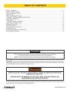
SAFETY SYMBOLS ..................................................................................................................................................4
SAFETY PRECAUTIONS ..........................................................................................................................................5
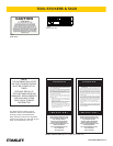
TOOL STICKERS & TAGS ........................................................................................................................................7
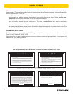
HOSE TYPES ............................................................................................................................................................8
HOSE RECOMMENDATIONS ..................................................................................................................................9
FIGURE 1. TYPICAL HOSE CONNECTIONS .......................................................................................................9
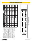
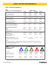
HTMA REQUIREMENTS .........................................................................................................................................10
OPERATION ............................................................................................................................................................ 11
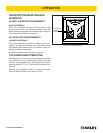
FIGURE 2. DIODE LOCATION ............................................................................................................................12
TOOL PROTECTION & CARE ................................................................................................................................13
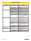
TROUBLESHOOTING ............................................................................................................................................14
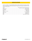
SPECIFICATIONS ................................................................................................................................................... 15
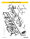
AL35 PARTS ILLUSTRATION ................................................................................................................................. 16
AL35 PARTS LIST ................................................................................................................................................... 17
AL35 MOTOR PARTS ILLUSTRATION ...................................................................................................................18
AL35 WIRING DIAGRAM ........................................................................................................................................ 19
TABLE OF CONTENTS