


AL35 User Manual ◄ 11
OPERATION PROCEDURES
1. Observe all safety precautions.
2.
CAUTION
Do not connect or otherwise apply power to an
electrical load until the alternator has come up to
speed.
Move the hydraulic circuit control to the “ON” posi-
tion. As the alternator comes up to speed, a maxi-
mum electrical load of 3500 W, single‑phase 60 Hz
alternating current, at 120 volts becomes available.
3. Connect the electrical loads.
CAUTION
Do not exceed the alternator’s rated 3500 W
capacity.
NOTE:
Output voltage is proportional to the RPM of the hy‑
draulic motor.
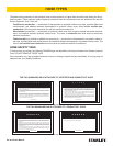
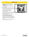
FLASHING THE FIELD
This procedure establishes residual magnetism in the
eld windings, to provide start‑up excitation and proper
output voltage levels.
1. Stop the alternator.
2. Remove the receptacle panel.
3. Using a 12 volt automotive battery, touch the posi-
tive lead to the positive (+) diode set with the white
or silver band, located on the rotor assembly. At the
same time touch the negative lead to the negative
(-) diode. Hold the leads against the diodes for 2-4
seconds.
NOTE:
Do not reverse the polarity of the leads. This may
cause damage to the diodes or the rotor or both.
4. Replace the receptacle panel and start the alterna-
tor.
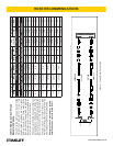
The recommended hose size is .500 inch/12 mm I.D. up
to 50 ft/15 m long and .625 inch/16 mm I.D. minimum up
to 100 ft/30 m.
PRE‑OPERATION PROCEDURES
ELECTRICAL GROUND
If required, ground the electrical load and alternator at
the ground lug on the alternator frame, lower right (as
viewed from the front).
CHECK POWER SOURCE
1. Using a calibrated owmeter and pressure gauge,
check that the hydraulic power source develops a
ow of 7–9 gpm/26–34 lpm at 2000 psi/140 bar.
2. Make certain the hydraulic power source is equipped
with a relief valve set to open at 2100 psi/145 bar
maximum.
CONNECT HOSES
1. Wipe all hose couplers with a clean, lint‑free cloth
before making connections.
2. Connect the hoses from the hydraulic power source
to the tool ttings or quick disconnects. It is a good
practice to connect return hoses rst and discon-
nect them last to minimize or avoid trapped pressure
within the tool.
3. Observe ow indicators stamped on hose couplers
to ensure that uid ow is in the proper direction.
The female coupler on the tool hose is the inlet cou-
pler.
4. Move the hydraulic circuit control valve to the ON
position to operate the tool.
NOTE:
If uncoupled hoses are left in the sun, pressure in‑
crease within the hoses may make them difcult to
connect. When possible, connect the free ends of
the hoses together.
OPERATION