


Series 780S Instruction Manual Chapter 3 Operation
IM-78S-B 3-13
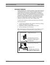
Instrument Validation
System electronics are verified by injecting a known input value and
confirming that the flow meter outputs the expected value. This test
confirms that the microprocessor, analog to digital and digital to
analog converters, the linearizer and the display are working prop-
erly. Sensor validation is accomplished by measuring the resistance
of the velocity and temperature sensors and comparing the results to
the NIST-traceable calibration data provided with the flow meter.
These tests confirm that your meter is working correctly and the
calibration variables did not drift, shift or change values.
To perform the instrument validation procedures you will need the
following equipment:
• certified digital multimeter with minimum 4 character resolution,
accuracy of at least ± 0.1% of range
• Calibration Certificate supplied with the flow meter
• small pot adjusting tool (screwdriver)
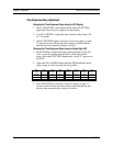
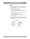
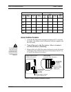
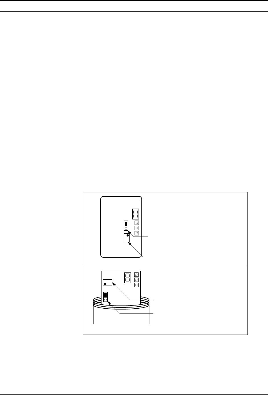
Before beginning the validation procedures, review Figure 3-3 and
Figure 3-4 to familiarize yourself with the component locations.
NEMA 4X Enclosures
J1 CAL/RUN jumper. Place in the
CAL position for validation, return to
RUN position for normal operation.
CAL
RUN
VR3
J1
Potentiometer VR3
J1 CAL/RUN jumper. Place in the
CAL position for validation, return to
RUN position for normal operation.
VR3
J1
Potentiometer VR3
Hazardous-Area Enclosures
CAL
RUN
Figure 3-3. Electronics Validation Component Locations