Series 780S Instruction Manual Chapter 2 Installation
IM-78S-B 2-7
Output Signal Wiring
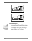
Output signal cable should be completely screened with a 100%
shield. You must use metal cable glands that provide cable screen
clamping. The cable screen should be connected to the gland and
shielded at both ends over 360 degrees. The shield should be ter-
minated to an earth ground.
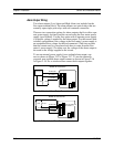
Flow meters are equipped with either a calibrated 0-5 VDC (0-10
VDC optional) or a calibrated 4-20 mA output signal. This linear
output signal represents 0-100% of the flow meter’s user full
scale.
DC Output Wiring
The 0-5 VDC (0-10 VDC optional) signal can drive a minimum load
of 1000 Ohms. Note: the optional 0-10 VDC output signal is not
available for power sources below 15 VDC.
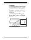
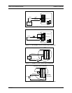
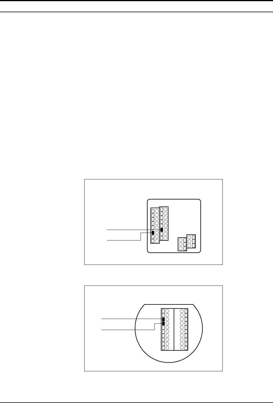
For 0-5 VDC or 0-10 VDC connections, connect to the terminals
marked Vout (+) and Vout (–) as shown below.
1
2
15
16
0-5 V out (+)
0-5 V out (–)
NEMA 4X Enclosures
Figure 2-8. DC Output Signal Connections
1
2
3
4
5
6
7
8
9
10
20
19
18
17
16
15
14
13
12
11
0-5 V out (+)
0-5 V out (–)
Hazardous-Area Enclosures
Figure 2-9. DC Output Signal Connections


