


Series 780S Instruction Manual Chapter 2 Installation
IM-78S-B 2-11
1
2
3
4
5
6
7
8
9
10
20
19
18
17
16
15
14
13
12
11
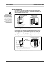
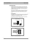
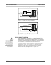
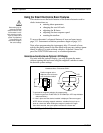
Hazardous-Area Enclosures
Load Load
LO ALARM (–)
AC or DC
power supply
HI ALARM (–)
ALRM COM
Figure 2-17. Isolated Alarm Output Connections
1
2
3
4
5
6
7
8
9
10
20
19
18
17
16
15
14
13
12
11
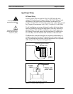
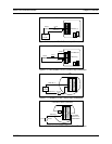
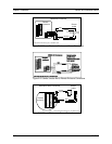
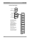
Hazardous-Area Enclosures
Load Load
LO ALARM (–)
HI ALARM (–)
ALRM COM
DC POWER OUT
Figure 2-18. Non-Isolated Alarm Connections
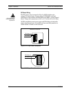
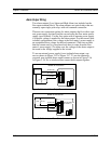
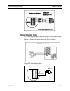
Remote Sensor Probe Wiring
When connecting the sensor probe to a remotely mounted flow
meter enclosure, use only factory supplied cables. The electronics,
sensors and interconnecting cables supplied by Sierra Instruments
are calibrated as a complete precision mass flow circuit.
To connect the sensor probe to a remotely mounted electronics
enclosure, see Figure 2-19 or Figure 2-21. To make wiring
connections from a sensor probe junction box to a remotely
mounted enclosure, see Figure 2-20 or Figure 2-22.
Caution!
Changing the length of ca-
bles or interchanging sen-
sors or sensor wiring will af-
fect the accuracy of the flow
meter. You cannot add or
subtract wire length without
returning the meter to the fac-
tory for recalibration.