


Page 18 - ASTRA/G55
Pin 13 GRAY: Auxiliary 1 Output (-) 500 mA. Connect to a relay for an optional feature such as trunk release,
etc. This output may be programmed for momentary, timed, or latched operation.
Pin 14 GREEN/WHITE: Brake Input (+). Connect to the wire that shows +12V when pressing the brake.
The Green/white wire is a safety shutdown wire that must be connected.
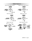
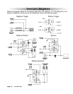
Pin 15 WHITE: Parking Light Output (+/-) relay. Connect the White wire to the circuit that shows +12V or
ground only when the parking lights are on and set the internal parking light relay jumper to the proper
polarity. For parking light circuits exceeding 10 amps, a relay is required. For vehicle’s with independent
left and right parking light circuits, diodes must be installed to keep the circuits separate. NOTE: Do
not connect the WHITE wire to the vehicle’s headlight circuit.
Pin 16 RED WIRE: Module Power Input (+). Connect to a constant source of +12V.
Plug-in Connectors
4-Pin Data Bus Port ( plug in bypass module)
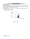
2-Pin Blue Connector: Valet switch port. Mount program switch in an area that is easily accessible from
the driver’s position.
2-Pin Red Connector: LED port. Mount LED in an area where it may be easily seen from either side of
the vehicle.
5-Pin White Connector: Two Way Receiver Connector.
3-Pin White Door Lock Connector: Door lock port.
· BLUE WIRE - negative unlock output (-) 500mA.
· RED WIRE - (+) Not used
· GREEN WIRE - negative lock output (-) 500mA.
4-Pin White Connector: Dual stage shock sensor port. (Auxiliary (-) Start Activation Pulse
for ASTRA 1000RS, see page 23)
5-PIN RED Remote Start Relay Module: supplys negative output for additional relays
( optional connects to additionl remote start relay module)