


ASTRA/G55 - Page 17
System
Wiring
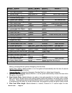
6-Wire Starter Harness
Pin 1 RED - A: Main Power Input A (+). Connect to the battery or constant power wire at the ignition switch
with a minimum 30 Amp supply. Remove the fuse until the installation is complete and all wiring is
checked.
Pin 2 RED - B: Main Power Input B (+). Connect to the battery or constant power wire at the ignition switch
with a minimum 30 Amp supply. Note: if connecting at the ignition switch it is highly recommended
to use separate power wires for each Red wire, each with a minimum 30A supply. Remove the fuse
until the installation is completed and all wiring is checked.
Pin 3 BROWN: Second Ignition Output (+). The Brown wire provides +12V for a second ignition wire. This
wire may instead be programmed for use as a second accessory or second starter wire.
Pin 4 ORANGE: Accessory Output (+). Connect to the accessory wire coming from the ignition switch that
supplies power to the heater/air-conditioner. Some cars may have multiple accessory wires.
Pin 5 YELLOW: Ignition Output (+). Connect to the main ignition wire that provides +12V when the ignition
is on and while cranking the starter.
Pin 6 VIOLET: Starter Output (+). Connect to the the vehicle’s starter wire.
16-Pin Main Harness
Pin 1 BROWN/WHITE: Horn Output (-) 500 mA. Connect to a relay to activate the vehicle’s horn when the
alarm is triggered.
Pin 2 BLACK/GRAY: Tach Input. Connect to the vehicle’s tach wire or a fuel injector wire if the tachless
mode does not provide satisfactory operation.
Pin 3 BROWN: Siren Output (+) 3A. The Brown wire must connect to the siren’s red wire. The Black siren
wire must be grounded.
Pin 4 GREEN: Negative Door Input (-), Connect to the door switch circuit wire that shows ground when the
door is open.
Pin 5 VIOLET: Positive Door Input (+), Connect to the door switch circuit wire that shows +12V when the
door is open. This type of door circuit is usually found on Ford
vehicles.
Pin 6 YELLOW : Factory Rearm (-), this wire will pulse negative upon remote start shut down.
Pin 7 WHITE/BLACK: Hood Pin Input (-). Connect the to the hood pin switch. The switch must provide a
ground output when switch is opened.
Pin 8 BLACK: Ground Input (-), The Black wire must connect to a solid chassis ground. Clean away any paint
or dirt to insure the best possible ground.
Pin 9 BLACK/WHITE: Dome Light Output (-) 500 mA. Connect to the wire that activates the vehicle’s dome
light, usually the door pin switch wire. (see Green and Violet door trigger wires).
Note: Must Use
Relay.
Pin 10 WHITE/VIOLET: Factory Disarm Output (-) 500 mA. The Violet/white wire provides a ground output
on disarming and before remote starting to disarm a factory security system. Connect to the wire that
requires a ground pulse to disarm the factory security system.
Pin 11 BLUE/ORANGE: Ground When Running Output (-) 500 mA. Connect to an optional factory security
bypass module if required.
Pin 12 ORANGE: Armed Output (-) 500 mA. The Orange wire provides a ground output while armed to
activate a relay for starter defeat and anti-grind protection.