


6
S4359146
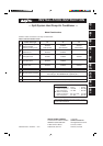
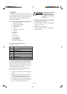
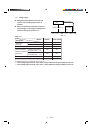
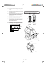
Table 1-3 TH (Ceiling-Mounted)
Part Name Figure Q’ty Remarks
Special washer
4
Drain insulator 1
Flare insulator
1 Set
Drain hose adaptor 1
Drain hose clamp 4
Insulating tape
2
1
Vinyl clamp 2
Full-scale installation
1
diagram
Sealing putty 1
Drain hose 1
Tube connector 1
For temporarily suspending
indoor unit from ceiling
For drain hose joint
For wide tube joints
For wide tube and drain hose joint
For wide flare joints
For ends of flare insulator
For determining suspension
bolt pitch
For sealing recessed portion of power supply
For sizing up of narrow tube from 1/4 in. to 3/8 in.
(only for 24 type)
T5
T3
Black
White
(heat-resisting)
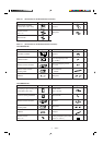
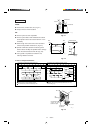
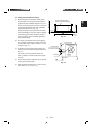
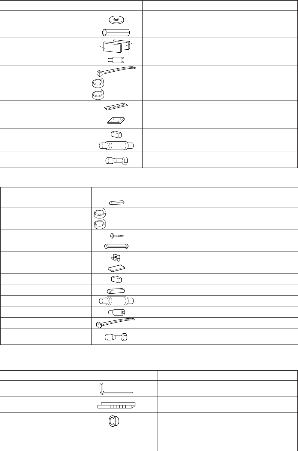
Table 1-5 (Outdoor Unit)
Part Name Figure
Q’ty
Remarks
Hexagonal Wrench 1
Grommet 1
Bushing 1
Installation Instruction 1
Owner’s manual 1
To open and shut the Narrow Tube Service Valve
For protecting refrigerant pipe by attaching to the
edge of Tubing Outlet
For protecting inter-unit control line by attaching to
the edge of wiring outlet
(Black)
(White)
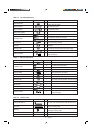
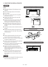
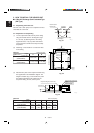
Table1-4 UH (Concealed-Duct)
Part Name Figure
Q’ty
Remarks
Flare insulator 2
Insulating tape
2
2
Tapping screw TOTA4-10
14 or 20 or 24
Jumper cable* 1
Hose band 1
Packing 1
Sealing putty 1
Drain insulator 1
Drain hose 1
Drain hose adaptor 1
Clamp 9
Tube connector 1
For wide and narrow tubes
For wide and narrow tubes
For wide and narrow tube flare nuts
For air intake duct connection
For increasing the fan speed
For securing drain hose
For drain joint
For sealing recessed portion of power supply
For drain joint
For securing drain hose & refrigerant tubing
For sizing up of narrow tube from 1/4 in. to 3/8 in.
(only for 24 type)
* Jumper cable is housed inside the electrical component box.