


41
S4359146
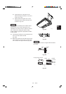
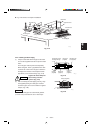
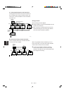
5. ELECTRICAL WIRING
5-1. General Precautions on Wiring
(1) Before wiring, confirm the rated voltage of the
unit as shown on its nameplate, then carry out
the wiring closely following the wiring diagram.
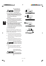
(2) Provide a power outlet to be used exclusively for
each unit, and a power supply disconnect and
circuit breaker for overcurrent protection should
be provided in the exclusive line.
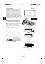
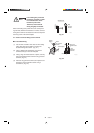
(3) To prevent possible hazards from insulation
failure, the unit must be grounded.
(4) Each wiring connection must be done in accor-
dance with the wiring system diagram. Wrong
wiring may cause the unit to misoperate or
become damaged.
(5)
Do not allow wiring to touch the refrigerant tubing,
compressor, or any moving parts of the fan.
(6) Unauthorized changes in the internal wiring can
be very dangerous. The manufacturer will
accept no responsibility for any damage or
misoperation that occurs as a result of such
unauthorized changes.
(7)
Regulations on wire diameters differ from locality to
locality. For field wiring rules, must follow your
LOCAL ELECTRICAL CODES before beginning.
You must ensure that installation complies with all
relevant rules and regulations.
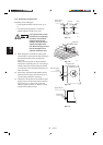
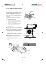
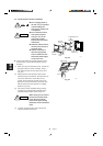
(8) To prevent malfunction of the air conditioner
caused by electrical noise, care must be taken
when wiring as follows:
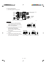
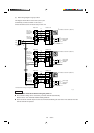
● The remote control wiring and the inter-unit
control wiring should be wired apart from the
inter-unit power wiring.
● Use shielded wires for inter-unit control wiring
between units and ground the shield on both
sides.
(9) If the power supply cord of this appliance is
damaged, it must be replaced by a repair shop
appointed by the manufacture, because special
purpose tools are required.
(10) All wiring must be used class 1.
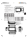
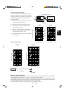
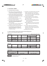
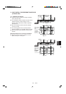
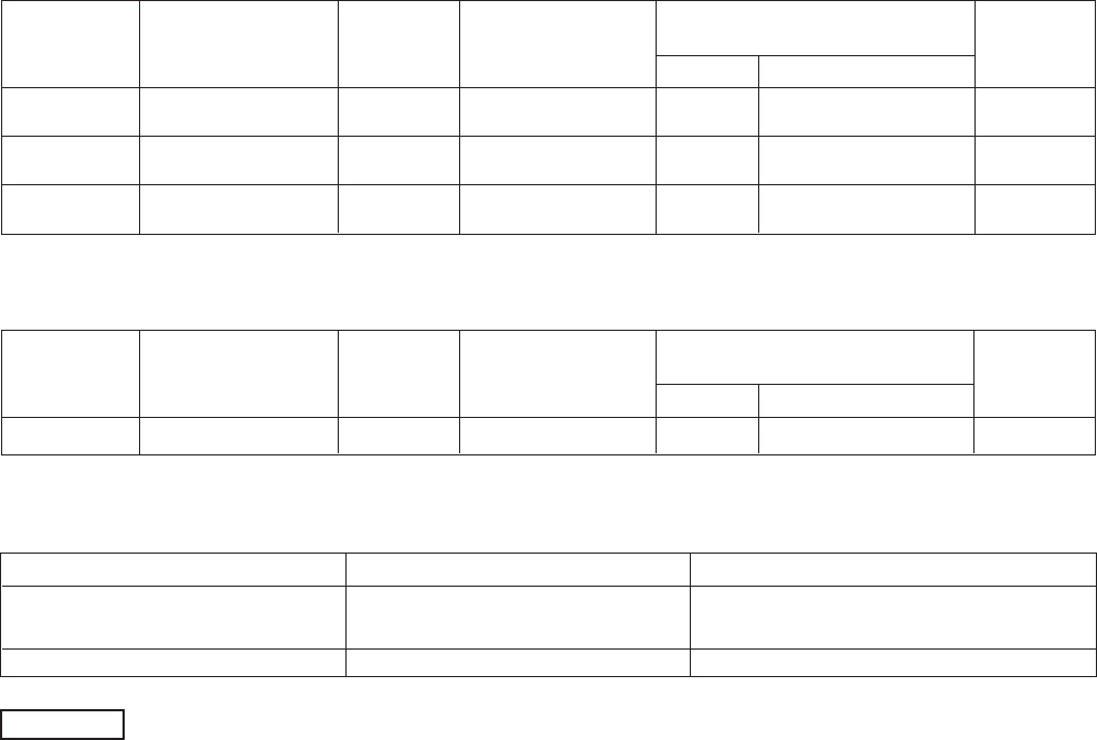
Model Name
(A) Power Supply Power Supply Terminal Base
Capacity Max. Wire Diameter
CH2442 3/4 in. 25 A 50 A
AWG #6 1-1/4 in.
CH3642 3/4 in.
35 A/40 A (230/208 V)
50 A
AWG #6 1-1/4 in.
CH4242 3/4 in. 45 A 50 A
AWG #6 1-1/4 in.
Trade size
of Conduit
Trade size
of Conduit
MOP
(Fuse or HACR
type circuit braker)
AWG #12
Max. length 69 ft.
AWG #12
Max. length 69 ft.
AWG #10
Max. length 67 ft.
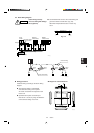
(C) Inter-Unit Control Wiring (D) Remote Control Wiring (E) Control Wiring For Group Control
AWG #18 (0.75 mm
2
) AWG #18* (0.75 mm
2
) AWG #18*
2
(0.75 mm
2
)
Use high voltage wire (300 V)
*1
Max. 3,300 ft. Max. 1,650 ft. Max. 1,650 ft. (Total)
NOTE
*
1
With ring type wire terminal.
*
2
Wire joint connection.
Control Wiring
Type
Trade size
of Conduit
Trade size
of Conduit
Indoor Unit
(B) Power Supply Power Supply Terminal Base
Capacity Max. Wire Diameter
X, K, T, U Max. length 330 ft. 3/4 in. 15 A 25 A
AWG #10 3/4 in.
MOP
(Fuse or HACR
type circuit braker)
5-2. Recommended Wire Length and Wire Diameter for Power Supply System
Must follow LOCAL ELECTRICAL CODES for wiring.
Outdoor Unit * AWG = American Wire Gauge