


22
22
2
K
22
S4359146
Fig. 3-21
Fig. 3-20
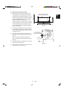
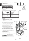
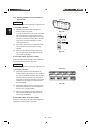
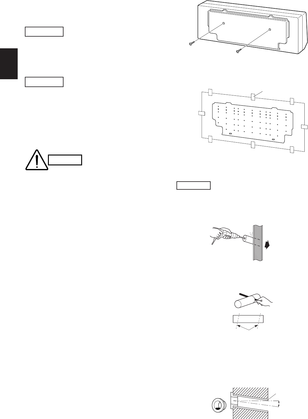
Hole should be made at a slight downward slant to the
outdoor side.
NOTE
Indoor
side
Outdoor
side
0066_T_
I
Fig. 3-19
Tape
Full-scale installation diagram
0940_T_I
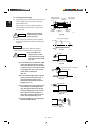
Cut at slight angle
PVC pipe (locally purchased)
0941_T_I
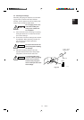
Plastic
cover
INSIDE
Wall
Slight
angle
PVC pipe
OUTSIDE
0942_K_
I
Wall fixture
Set screws only for transportation
1390_T_I
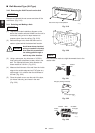
■ Wall-Mounted Type (KH Type)
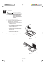
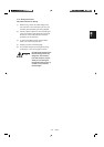
3-10. Removing the Wall Fixture from the Unit
Remove and discard the set screws and take off the
wall fixture. (Fig. 3-19)
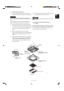
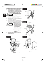
3-11. Selecting and Making a Hole
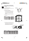
(1) Tape the full-scale installation diagram on the
wall at the location selected. Make sure the unit is
horizontal, using a level or tape measure to
measure down from the ceiling. (Fig. 3-20)
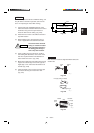
(2) Before drilling a hole, check that there are no
studs or pipes behind the determined location.
Avoid area where electrical
wiring or conduit is located.
Also take this precaution if
the tubing goes through a
wall at any other location.
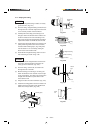
(3) Using a sabre saw, key hole saw or 3-5/32 in.
hole-cutting drill attachment, make a hole in the
wall. The required minimum hole diameter for
these models is 3-3/16 in. (Fig. 3-21)
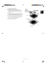
(4) Measure the thickness of the wall from the inside
edge to the outside edge and cut PVC pipe at a
slight angle 1/4 in. shorter than the thickness of
the wall. (Fig. 3-22)
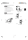
(5) Place the plastic cover over the end of the pipe,
(for indoor side only) and insert in the wall.
(Fig. 3-23)
Fig. 3-23
Fig. 3-22
CAUTION
KH2442
KH2442