


RoyalTek GPS Receiver REB-2000/REB-12R REV-2000 Operational Manual
31
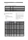
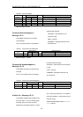
Integration
Interval
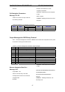
2 0013 Ms 19
Track Loop
Iteration
2 003F 63
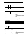
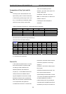
Payload Length:51 bytes per satellite tracked (up to 12)
1.For further information,go to Table 45
2.Multiply by (1000
÷
4
π
)
÷
2
16
to convert to Hz.
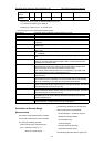
The meaning of I.D.5 is described as following table
Message ID: Each SiRF binary message is defined based on the ID.
Channel: Receiver channel where data was measured (range 1-12).
SVID: PRN number of the satellite on current channel.
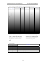
State: Current channel tracking state (see Table 45)
Bit Number: Number of GPS bits transmitted since Sat-Sun midnight (in Greenwich) at a
50 bps rate.
Millisecond Number: Number of milliseconds of elapsed time since the last received bit(20 ms
between bits)
Chip Number: Current C/A code symbol being transmitted (range 0 to 1023 chips;1023
chips=1 ms).
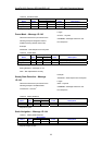
Code Phase: Fractional chip of the C/A code symbol at the time of sampling(scaled by
2
-16
,=1/65536)
Carrier Doppler: The current value of the carrier frequency as maintained by the tracking
loops.
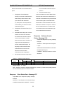
Receiver Time Tag: This is the count of the millisecond interrupts from the start of the receiver
(power on) until the measurement sample is taken. The ms interrupts are
generated by the receiver clock.
Delta Carrier Phase: The difference between the carrier phase(current) and the carrier
phase(previous). Units are in carrier cycles with the LSB= 0.00185 carrier
cycles. The delta time for the accumulation must be known.
Note –Carrier phase measurements are not necessarily in sync with code
phase measurement for each measurement epoch.
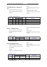
Search Count: This is the number of times the tracking software has completed full satellite
signal searche.s
C/No: Ten measurements of carrier to noise ratio(C/No) values in dBHZ at input to
the receiver.Each value represents 100 ms of tracker data and its sampling
time is not necessarily in sync with the code phase measurement.
Power Loss Count: The number of times the power detectors fell below the threshold between the
present code phase sample and the previous code phase sample. This task is
performed every 20 ms (max count is 50).
Phase Loss Count: The number of time the phase lock fell below the threshold between the
present code phase sample and the previous code phase sample. This task is
performed every 20 ms (max count is 50).
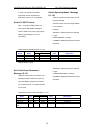
Integration Interval: The time in ms for carrier phase accumulation . This is the time difference (as
calculated by the user clock) between the Carrier Phase(current) and the
Carrier Phase(previous).
Track Loop Iteration: The tracking Loops are run at 2 ms and 10 ms intervals. Extrapolation values
for each interval is 1 ms and 5 ms for range computations.
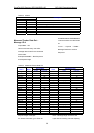
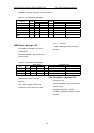
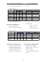
Calculation of Pseudo-Range
Measurements
The pseudo-range measurement in meters
can be determined from the raw track data
by solving the following equation:
Pseudo-range (PR) = {Received Tine
(RT) – Transmit Time (TT)} * C
where C = speed of light
The following variables from the raw track
data are required for each satellite:
Bit Number (BN) – 50 bits per second
Millisecond Number (MSN)
Chip Number (CN)
Code Phase (CP)
Receiver Time Tag (RTTag)
Delta Carrier Phase (DCP)
The following steps are taken to get the psr