


RoyalTek GPS Receiver REB-2000/REB-12R REV-2000 Operational Manual
8
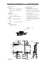
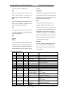
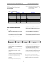
communicate with a PC serial port.
RXA
This is the main receiving channel and is
used to receive software commands to the
Engine board from user written software.
RXB
This is the auxiliary receive channel and is
used to input differential corrections to the
Engine board to DGPS navigation.
TXA
This is the main transmit channel and is used
to output navigation and measurement data
to user written software.
TXB
Reserved.
RESET
This pin provides an active-low reset input to
the Engine board. It causes the board to reset
and start searching for satellites. PB Reset is
an optional input and, if not used, should be
tied high.
TIMEMARK
This pin provides one pulse per second output from
the engine board which is synchronized to within one
microsecond of GPS time. The output is a TTL
negative level signal with negative logic.
VBAT
This is the battery backup supply that
powers the SRAM and RTC when main
power is removed. Typical current draw is 10
uA. Without an external backup battery or on
board battery, engine board will execute a
cold start after every turn on. To achieve the
faster start-up offered by a hot or warm start,
either a backup battery must be connected
or battery installed on board.
BOOTSEL
This is for software upgrade when pull high
to 3.3V. It can be left non-connected for
normal operation because of internal 68kΩ
pull low resistor.
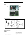
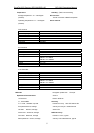
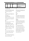
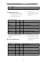
REB-12R LXHA version
Pin NO Signal
Name
I/O Description Characteristics
1 VANT I Antenna DC Voltage Depending on the user requirement..
2 VCC_5 I +5V DC Power Input DC +5V ± 10%.
3 VBAT I User Supply +3.3V DC
Power Input*
DC +3.3V ± 10%.
Current
≤
10mA
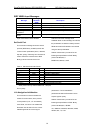
4 Reserved Reserved DC +3V ± 10%
5 RESET I Reset Input, Active Low Vih>2.3V , Voh>VCC-1.5V
Vil<0.8V , Vol<0.4V
6 RESERVED - Reserved
7 RESERVED - Reserved
8 RESERVED - Reserved
9 RESERVED - Reserved
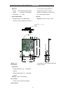
10 GND G Ground
11 TXA O NMEA Output
9600bps, 8 data bits,
no parity, 1 stop bit
Voh
≥
VCC-0.5, Vo1
≤
0.4V, Ioh =
-200uA
Io1 = 1.6mA
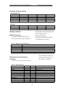
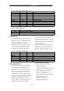
12 RAX I Serial Data Input A
VCC*0.7
≤
Vih
≤
VCC+0.3V,
-0.3V
≤
Vil
≤
VCC*0.2V
13 GND G Ground
14 TXB O Serial Data Output B
Voh
≥
VCC-0.5, Vo1
≤
0.4V, Ioh =
-200uA
Io1 = 1.6mA
15 RXB I RTCM 104 differential
GPS input.
VCC*0.7
≤
Vih
≤
VCC+0.3V
-0.3V
≤
Vil
≤
VCC*0.2V
16 GND G Ground
17 RESERVED - Reserved