


6
DYNAMIXEL
RX-64
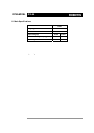
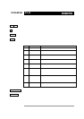
PIN1: GND
PIN2: VDD(12V~21V)
PIN3: D+
PIN4: D-
PIN5: NC or VCC(5V)
PIN5: NC or VCC(5V)
PIN4: D-
PIN3: D+
PIN2: VDD(12V~21V)
PIN1: GND
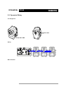
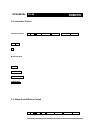
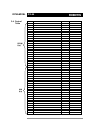
2-3. Dynamixel Wiring
Pin Assignment The connector pin assignments are as the following. The two connectors on the
Dynamixel are connected pin to pin, thus the RX-64 can be operated with only one
connector attached.
( Note : The pin number of connector’s edge cut side is PIN1)
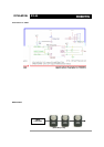
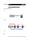
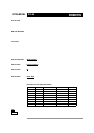
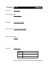
Wiring Connect the RX-64 actuators pin to p in as shown below. Many RX-64 actuators ca n be
controlled with a single bus in this manner.
Main Controller To operate the Dynamixel actuators, the main controller must support TTL level RS485
UART. A proprietary controller can be used, but the use of the D yn amixel controller CM-2
PLUS is recommended.
Control Box “CM-2