


11
DYNAMIXEL
RX-64
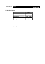
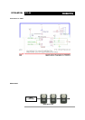
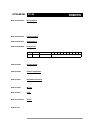
The meanings of each packet byte definition are as the following.
0XFF 0XFF The two 0XFF bytes indicate the start of the packet.
ID The unique ID of the Dynamixel un it returning the packet. The initial value is set to 1.
LENGTH The length of the packet where its value is “Number of parameters (N) + 2”
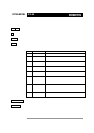
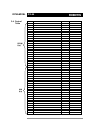
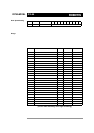
ERROR The byte representing errors sent from the Dynamixel unit. The meaning of each bit is
as the following.
Bit Name Details
Bit 7 0 -
Bit 6 Instruction Error
Set to 1 if an undefined instruction is sent or an action
instruction is sent without a Reg_Write instruction.
Bit 5 Overload Error
Set to 1 if the specified maximum torque can't control the
applied load.
Bit 4 Checksum Error Set to 1 if the checksum of the instruction packet is incorrect.
Bit 3 Range Error Set to 1 if the instruction sent is out of the defined range.
Bit 2
Overheating
Error
Set to 1 if the internal temperature of the Dynamixel unit is
above the operating temperature range as defined in the
control table.
Bit 1
Angle Limit
Error
Set as 1 if the Goal Position is set outside of the range
between CW Angle Limit and CCW Angle
Limit.
Bit 0
Input Voltage
Error
Set to 1 if the voltage is out of the operating voltage range as
defined in the control table.
PARAMETER0…N Used if additional information is need ed.
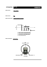
CHECK SUM The computation method for the ‘Check Sum’ is as the following.
Check Sum = ~ (ID + Length + Instruction + Parameter1 + ... Parameter N)
If the calculated value is larger than 255, the lower byte is defined as the checksum
value. ~ represents the NOT logic operation.