


13
English Translation by: Tribotix Pty Ltd
www.tribotix.com
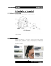
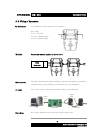
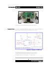
DYNAMIXEL
DX-116
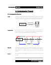
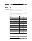
Control Table The Control Table consists of data for conditions and movement of the
Dynamixel. By writing the values in the control table, you can move the
Dynamixel and detect the condition of the Dynamixel.
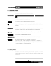
RAM and EEPROM The data values for the RAM Area will be set to the default initial values on
power on. The data values for the EEPROM Area are non-volatile and will be
available next power on.
Initial Value The Initial Value column of the control table shows the Factory Default Values
for the case of EEPROM Area Data. For the RAM Area Data, the initial value
column gives the power on data values.
Please note the following meanings for data assigned to each address in the
control table.
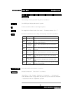
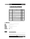
Address 0x00,0x01 Model Number
. In the case of the DX-116, the value is 0X0074(116).
Address 0x02 Firmware Version
.
Address 0x03 ID
. Unique ID number to identify the Dynamixel. Different ID’s are required to
be assigned to “linked” Dynamixels.
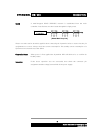
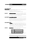
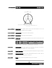
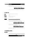
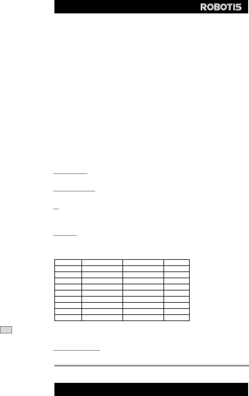
Address 0x04 Baud Rate
. Determines the Communication Speed. The Calculation method is:-
Speed(BPS) = 2000000/(Address4+1)
Note A maximum Baud Rate error of 3% is within the UART communication tolerance.
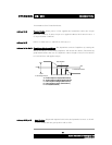
Address 0x05 Return Delay Time
. The time taken after sending the Instruction Packet, to
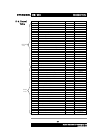
Data Value as per Major Baud Rate
Address4
BPS Set Target BPS Error
1 1000000.0 1000000.0 0.000%
3 500000.0 500000.0 0.000%
4 400000.0 400000.0 0.000%
7 250000.0 250000.0 0.000%
9 200000.0 200000.0 0.000%
16 117647.1 115200.0 -2.124%
34 57142.9 57600.0 0.794%
103 19230.8 19200.0 -0.160%
207 9615.4 9600.0 - 0.160%