9
\L
11
12
15
14
13
14
I
'2
2
0
d3
nlmml
8
9
5
6
\
4
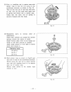
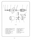
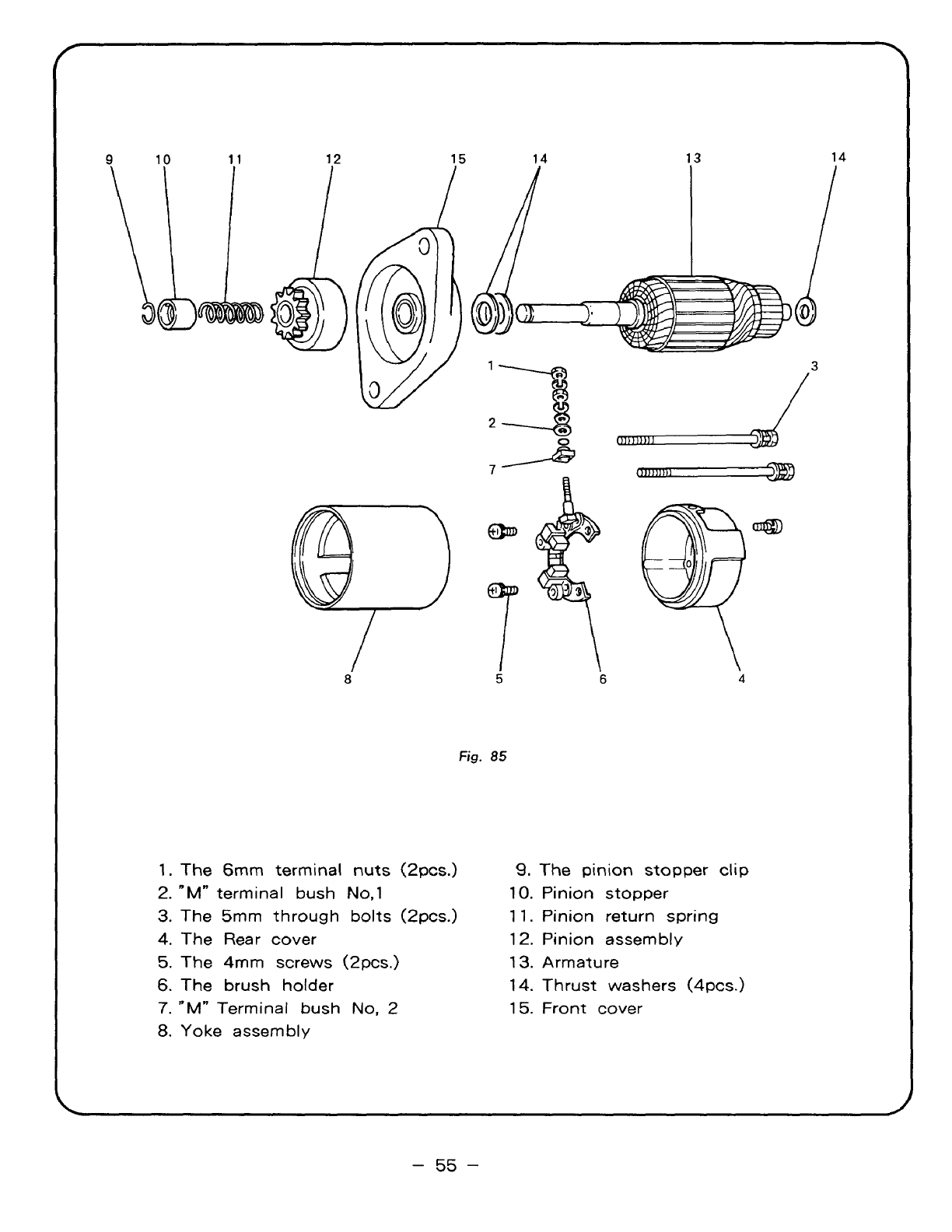
Fig.
85
1.
The
6mm
terminal nuts
(2pcs.)
2.
"M"
terminal bush
No,1
3.
The 5mm through bolts
(2pcs.)
4.
The Rear cover
5.
The
4mm
screws
(2pcs.)
6.
The brush holder
7.
"M"
Terminal
bush
No,
2
8.
Yoke assembly
9.
The
pinion
stopper
clip
10.
Pinion stopper
1 1.
Pinion return spring
12.
Pinion assembly
13.
Armature
14.
Thrust washers (4pcs.)
15.
Front cover
-
55
-


