


6-2
BASE
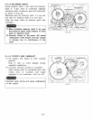
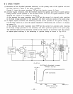
THEORY
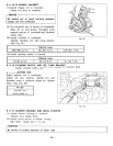
(1)
Revolution
of
the flywheel generates electricity on the primary side
of
the ignition coil, and
the base current
I1
flows to the power transistor.
Current
I1
turns the power transistor "0N"and the electric current
Iz
flows.
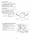
(2)
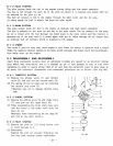
At lower engine revolution, when the flywheel reached the ignition point the low speed ignition
timing controll circuit operates to
run
the base current
13
to turn the signal transistor
A
"ON"
allowing the current
I1
to bypass as current
14.
At
this
moment the power transistor turns "0FF"and the current
I2
is
abruptly shut resulting
in the high voltage generated in the secondary coil which produces sparks at the spark plug.
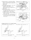
(3)
At higher engine revolution, the advancing controll circuit operates at the
1
ignition timing to
run the base current
k
to turn the signal transistor
B
"0N"allowing the current
I1
to
bypass
as current
Is.
At this moment
the
power transistor
turns
"0FF"and
the current
Iz
is
abruptly
shut
resulting
in the high voltage generated in the secondary coil which produces sparks at the spark plug.
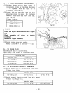
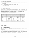
The operating timing
of
the advancing controll circuit advances in accordance with the increase
of engine speed resulting in the advancing
of
ignition timing
as
shown in Fig.
62
(b).
ELECTRONIC ADVANCING FLYWHEEL
MAGNETO SYSTEM
(B.T.D.C.)
c
,
STEP
ADVANCING
500
1000
2000
3000(r.p.m.)
ENGINE REVOLUTION
Fig.
62 (b)
-
43
-