


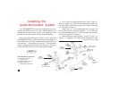
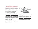

Installing the ‘quick-disconnect’ system
continued from preceding page
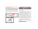
cable anchor “E” to part “A,” and cable anchor “F” to part
“B,” using the supplied ½" x 1" bolts and nuts.
Do not tighten any of the bolts — leave them loose
for now — they will be tightened later.
Use all mounting hardware, the safety plates, and
the cable anchors. If all supplied materials are not
used, the quick-disconnects, the quick-disconnect
bases, or other components may vibrate loose, which
may cause property damage, personal injury or even
death.
7
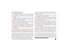
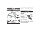
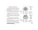
safety
plate
vertical pin of
quick-disconnect
part “A”
linch pin
QD
base
Figure 2
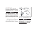
vehicle
mounting
bracket
long safety
cable attachment
short safety
cable attachment
lower vertical
pin of QD base
top hole
of QD
base
WARNING
The quick-disconnects must be centered on the
mounting brackets. If they are attached too far to the
left or the right, the tow bar will not be centered on
the towed vehicle, which will cause excessive tire
wear and other consequential, non-warranty damage.
2. Now, attach both quick-disconnect (“QD”) bases (and
the QD crossbar) by lowering them so that the vertical
pins of parts “A” and “B” extend upward through the top
holes of the QD bases (Figure 2). At the same time, be
certain the lower vertical pins of each QD base slide
through the lower holes on parts “A” and “B” (Figure 2).
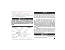
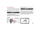
3. Both linch pins must be inserted through the upper
holes in the vertical pins in parts “A” and “B,” as shown
in Figure 2.
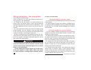
Both linch pins must be locked. The rings (Figure 3)
are spring-loaded — they must be snapped over the pin,
as shown in Figure 3, with the curved side of the linch
pin touching the ring (as shown in Figure 4), in order to
keep the QD bases secure.
Towing vibrations will force the linch pins out un-
continued on next page
CAUTION
WARNING