


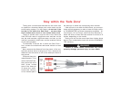

Wiring instructions — six-wire system
continued from preceding page
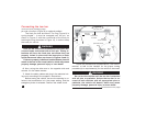
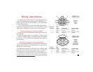
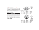
5. If your motorhome does not have the correct wiring
socket already, you can replace it with the new socket
for the six-wire cord, and connect the appropriate wires
to the new socket, according to Figure 15.
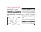
6. Now, connect the six-wire electrical cord to the mo-
torhome and to the towed vehicle. Test the towed vehi-
cle’s turn signals, tail lights and brake lights to ensure
they mimic the motorhome’s.
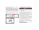
If the plugs and sockets are not properly wired, the
electrical connection will not function, and the towed
vehicle’s turn signals and brake lights will not mimic
those of the motorhome.
Drivers behind the towed vehicle will not be alert-
ed by turn signals or brake lights, which may result
in a traffic accident, causing property damage, person-
al injury or even death.
15
5
6
1
3
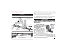
Socket Pin Wire
Number Color Motorhome Towed Vehicle
1 ...............Red .............Brake light................ Brake light
2 ...............Black...........Auxiliary.................... Auxiliary
3 ...............Green..........Right turn ................. Right turn
4 ...............Brown .........Taillight..................... Taillight
5 ...............White ..........Ground...................... Ground
6 ...............Yellow.........Left turn.................... Left turn
front of
plug on
6-wire
cord
2
4
3
1
5
6
4
2
Socket Pin Wire
Number Color Motorhome Towed Vehicle
1 ...............Red .............Brake light................ Brake light
2 ...............Black...........Auxiliary.................... Auxiliary
3 ...............Green..........Right turn ................. Right turn
4 ...............Brown .........Taillight..................... Taillight
5 ...............White ..........Ground...................... Ground
6 ...............Yellow.........Left turn.................... Left turn
front of
6-wire
socket
on towed
vehicle and
motorhome
Figure 14
Figure 15
WARNING