


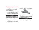

Installing the ‘quick-disconnect’ system
continued from preceding page
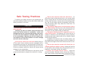
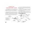
less they are properly locked in place over the verti-
cal pins on both quick-disconnects. Refer to Figures
3 and 4. Failure to install the linch pins properly will
result in tow bar malfunction, loss and damage to the
vehicle and property, personal injury or even death.
4. Adjust the spacing of QDs “A” and “B” until the QD
bases slide on and off easily. Now, torque all bolts to 75
ft./lbs.
Connecting the tow bar
Use caution when handling the tow bar — if your
hands, fingers or any part of your body are caught be-
tween moving components, they can be pinched, cut
or otherwise injured.
1. Follow the preceding section in this manual — “Install-
ing the ‘quick-disconnect’ system” — to attach the tow bar
quick-disconnects (“QDs”) and the QD bases.
Note: the quick-disconnect system is not used with
ROADMASTER ‘MS’ or ‘MX’ series mounting brackets. In-
stead, the tow bar is connected directly to the mounting
bracket with the base pins and linch pins.
With this exception, the instructions below apply.
2. Drive the vehicle within three or three-and-a-half feet
of the motorhome hitch receiver. The vehicle does not
have to be perfectly centered to the hitch receiver, just
close. Then, put the vehicle in gear (park), set the emer-
gency brake and chock one of the wheels.
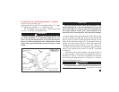
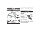
3. With the tow bar in the folded position (Figure 5), in-
sert the stinger into the motorhome hitch receiver, and
attach the stinger to the hitch receiver with the hitch pin
and clip (Figure 5).
continued on next page
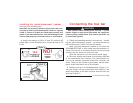
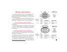
NO!
PIN WILL
VIBRATE
LOOSE
YES
PIN MUST BE
LOCKED
Figure 3
CAUTION
8
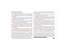
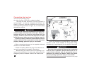
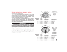
Figure 4
flat side of
linch pin
curved side
of linch pin
touches ring
ring
linch
pin