


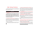
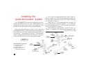
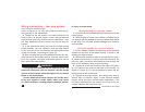

Figure 8
10
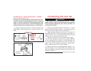
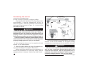
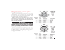
Connecting the tow bar
continued from preceding page
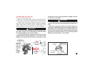
pin with a linch pin (Figure 9) or optional padlock.
The linch pin must be locked. The ring (Figure 9) is
spring-loaded — it must be snapped over the pin, as
shown in Figure 9, with the curved side of the linch pin
touching the ring (as shown in Figure 10), in order to keep
the base pin secure.
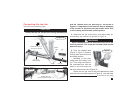
Both tow bar arms must be attached to the quick-dis-
connect bases and locked with a linch pin. Towing vi-
brations will force the linch pins out unless they are
properly locked in place over the base pins on both
quick-disconnect bases, as shown in Figures 9 and 10.
Failure to properly install and lock both base pins will
result in the loss of the towed vehicle, which may cause
property damage, personal injury or even death.
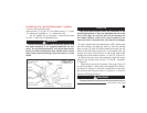
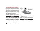
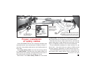
6. Now, swing the other arm to the opposite side and
connect it in the same manner.
7. Attach the safety cables and plug in the electrical wir-
ing cord, according to the supplier’s instructions.
Before towing the vehicle, be sure the steering is un-
locked, the transmission is in the proper setting, and the
emergency brake is released. Remove the wheel chock.
tow
bar
arm
base pin
inserted
base pin
to be inserted
quick-
disconnect
crossbar
base
pin
tab
c
c
linch
pin
quick-disconnect
base
quick-disconnect
base
WARNING
Check the manufacturer’s specifications, the owner’s
manual, or talk to the installer for the proper towing
procedure(s) or requirement(s) for the vehicle to be towed.
Do not tow the vehicle until the tow bar is attached
with all pins or padlocks. Unless the tow bar is se-
cured to both vehicles with all appropriate pins or
padlocks, the vehicle will detach, which may cause
property damage, personal injury or even death.
continued on next page
WARNING