8
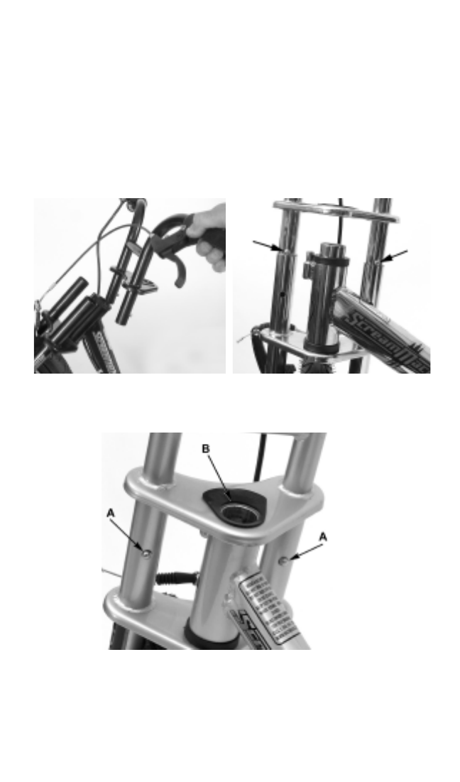
not tangled or twisted and so the brake cable and trigger wire are
routed as shown in 2c.
Insert the handlebar and upper fork crown assembly into the fork legs
as shown in Figure 2d. Press both the spring buttons (arrows, 2d)
and continue to slide the handlebar assembly into the fork until the
spring buttons engage the holes (A) as shown in Figure 2e, and the
steering tube extends through the upper fork crown (B). The fork stop
must be positioned in the slot in the upper crown. The fit between the
tubes is a close tolerance and may require a firm hand or taps with a
rubber mallet to nudge the handlebar all the way into the fork.
Figure 2c. Figure 2d.
Figure 2e.
Install the tensioning cap and adjusting screw as shown in Figure 2f.
Using an Allen key, snug the adjusting screw as shown in Figure 2g
until the fork crown is firmly seated against the steering bushings. This
is called “preloading.”


