12
Figure 3f.
Tightening the locknuts against the frame as shown in figure 3f.
Repeat the adjustment procedure in 6C as many time as necessary
to obtain the proper adjustment.
Check www.razor.com for tech updates or video clips on this and
other procedures.
NOTE: Although we make every effort to keep our manual up-to-
date, if your Electric Scream Machine does not look like this, then we’ve
made product improvements since this document was printed. Check
out the Razor website: www.razor.com for technical updates on the
latest service and adjustment procedures.
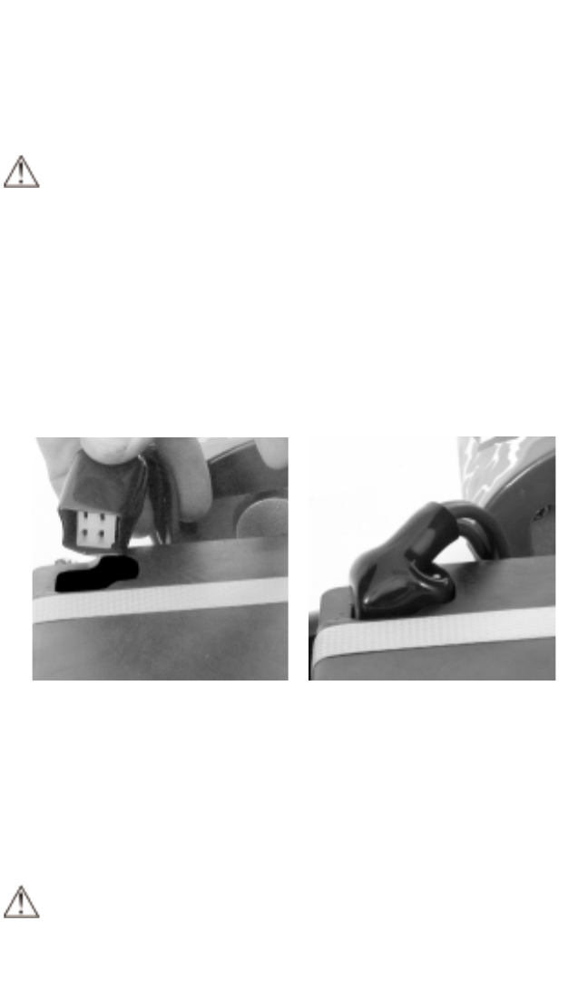
6D. Connect the motor.
The motor must be connected to the battery pack prior to installing the
seat. To connect, push the 4-pin coupling into the socket in the corner of
the battery pack as shown in Figures 4a and 4b
Figure 4a. Figure 4b.
6E. Attach the seat.
Flip the Electric Scream Machine on it’s side and, using the screws
shown in Figure 5a and the 4mm Allen key, fasten the seat to the frame
as shown in Figure 5b using one of the two positions: forward or aft,
depending on the rider’s size.
NOTE: The screws visible from the top of the seat attach the
mounting bracket to the plastic seat. Do not remove these screws.


