


Chapter 2: Installation 7
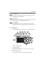
2.4 External Speaker Connections
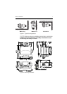
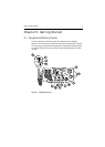
Located just below the power cord is a cable for connection to an optional
external speaker. Connect the white(+) wire and black (–) wire to the speaker
observing polarity as it is marked on the speaker. Mate the connector with its
counterpart on the rear of the radio. (See Figure 2-3 .) If not connecting an
external speaker, please leave the dust cover on the cable connector.
2.5 Grounding
While special grounding is not generally required for VHF radiotelephone
installations, it is good marine practice to properly ground all electronic
equipment to the boat’s earth ground system. The Ray54E can be connected to
ground by installing the supplied screw and lock washer in the threaded hole
labelled GND on the main unit’s rear panel just below the antenna jack. Then
attach a wire from this screw to the nearest ship’s earth ground connection
point. The recommended wire to be used for such grounding is #10 AWG.
2.6 GPS/NMEA Data
The Ray54E accepts NMEA 0183 (V1.5) data from a position determining
device (GPS) to provide the Latitude and Longitude position information
that is transmitted during a DSC Distress Call. When a valid NMEA signal is
detected, the GPS indicator appears on the LCD. When no valid NMEA
signal is detected, the NO GPS indicator appears.
Connect the NMEA OUT + and NMEA OUT– signals from the positioning
device to the GPS + (yellow) and GPS – (green) wires, respectively, of the
GPS cable. Mate the connector with its counterpart on the rear of the radio,
aligning the arrows on the two connectors. (See Figure 2-3 .) If not
connecting a GPS, please leave the dust cover on the cable connector.
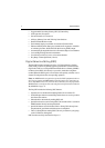
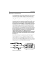
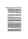
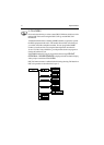
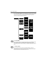
An example of how to make the connections using a suitable connector block
is shown in the following drawing. For specific instructions how to connect
your particular GPS, please refer to the handbook that came with that device.
Figure 2-4: GPS Wiring