


6
Heading Sensor Owner’s Handbook
Although every effort has been taken to ensure that they will perform
under all conditions, it is important to understand what factors could
affect the operation of the product.
The guidelines given here describe the conditions for optimum EMC
performance, but it is recognized that it may not be possible to meet all
of these conditions in all situations. To ensure the best possible
conditions for EMC performance within the constraints imposed by
any location, always ensure the maximum separation possible between
different items of electrical equipment.
For optimum EMC performance, it is recommended that wherever
possible:
• Raymarine equipment and cables connected to it are:
• At least 3 ft (1 m) from any equipment transmitting or cables
carrying radio signals e.g. VHF radios, cables and antennas. In
the case of SSB radios, the distance should be increased to 7 ft
(2 m).
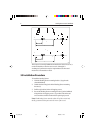
• More than 7 ft (2 m) from the path of a radar beam. A radar
beam can normally be assumed to spread 20 degrees above and
below the radiating element.
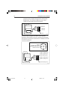
• The equipment is supplied from a separate battery from that used for
engine start. Voltage drops below 10 V in the power supply to our
products, and starter motor transients, can cause the equipment to
reset. This will not damage the equipment, but may cause the loss of
some information and may change the operating mode.
• Raymarine specified cables are used. Cutting and rejoining these
cables can compromise EMC performance and must be avoided
unless doing so is detailed in the installation manual.
• If a suppression ferrite is attached to a cable, this ferrite should not
be removed. If the ferrite needs to be removed during installation it
must be reassembled in the same position.
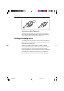
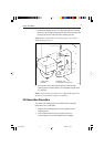
Suppression Ferrites
The following illustration shows typical cable suppression ferrites used
with Raymarine equipment. Always use the ferrites supplied by
Raymarine.
124_3c03.p65 09/05/01, 11:306