


Printed in Taiwan Audiovox Corp., 150 Marcus Blvd. Hauppauge, N.Y. 11788 Form No.
128-4515
+
FACTORY
REMOTEKEYLESS
ENTRYMODULE
+
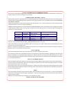
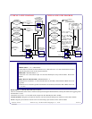
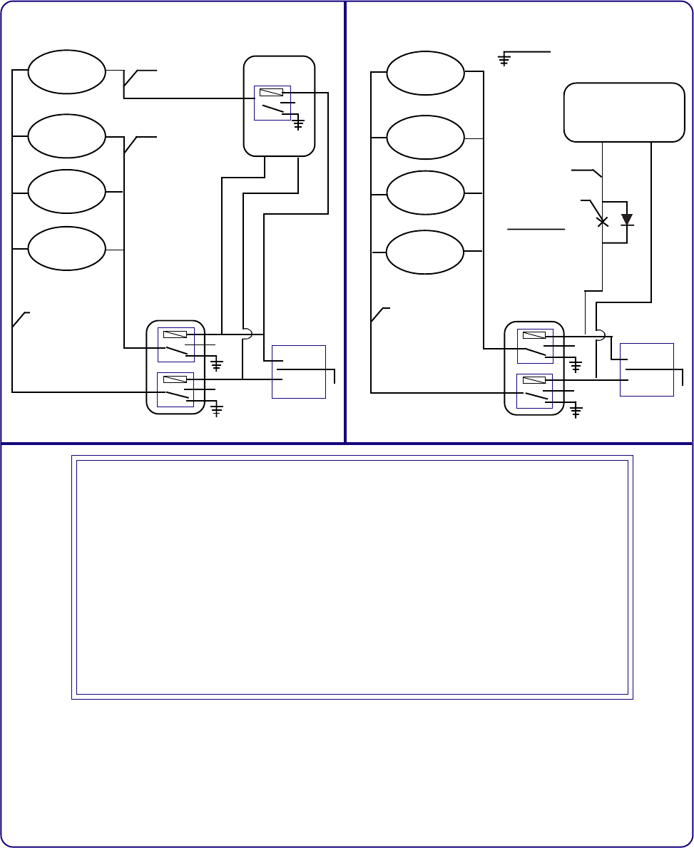
TYPICAL 2-STEP DIAGRAM
TYPICAL ONE-STEP DIAGRAM
+
FACTORY
REMOTEKEYLESS
ENTRYMODULE
ALL
UNLOCK
OUTPUT
ALL
LOCK
OUTPUT
ALL
UNLOCK
OUTPUT
ALL
LOCK
OUTPUT
CONNECT
"DISARMINPUT #1"
HERE.
CONNECT
"DISARMINPUT #2"
HERE.
UNLOCK
LOCK
LOCK
UNLOCK
+
+
CONNECT
"ARM" INPUT
HERE
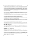
FACTORY
DOORLOCK
RELAYS
LEFTREAR
D/LMOTOR
RIGHTREAR
D/LMOTOR
RIGHTFRONT
D/LMOTOR
DRIVER'S
D/LMOTOR
DRIVER'S
D/LMOTOR
RIGHTFRONT
D/LMOTOR
RIGHTREAR
D/LMOTOR
LEFTREAR
D/LMOTOR
CONNECT
"ARM" INPUT
HERE
UNLOCK
LOCK
UNLOCK
DOORPANEL
LOCK/UNLOCK
SWITCH
DOORPANEL
LOCK/UNLOCK
SWITCH
LOCK
CONNECT
"DISARMINPUT #2"
TOCHASSISGROUND
FACTORY
DOORLOCKRELAYS
CONNECT "DISARM
INPUT #1" HERE
THEN CUT THE WIRE
AND ADD A DIODE,
AS SHOWN.
IF GROUND SWITCHED
DOOR LOCKS - TURN
DIODE TO FACE INTO THE
KEYLESS MODULE AND
CONNECT DISARM #2 TO
+12 VOLTS
DRIVER'S
DOOR UNLOCK
RELAY
WIRING THE ARM / DISARM INPUTS IN VEHICLES WITHOUT 2 STEP UNLOCK
GREEN WIRE : ( + or - ) ARM INPUT
Connectthiswiretothedriver'sdoorlockmotorwire,whichwillreceive+12voltswhenthedoorsarelocked
using the door panel switch or the remote transmitter.
RED WIRE : DISARM INPUT # 1
Connect this wire to the unlock output wire from the OEM keyless entry control module. Refer to the
diagram..
RED w/ BLACKTRACE WIRE : DISARM INPUT# 2
If theRed wire isswitched to+12 voltswhen the doorsare unlocked,connect the Redw/Black Tracewire
to ground.
If the Red wire is switched to ground when the doors are unlocked, connect the Red w/Black Trace wire
to +12 volts.
BLUE WIRE : (+) TRUNK TRIGGER SHUNT INPUT
This wire will determineif the vehicle’s trunk has beenopened using the OEM transmitter, andstop the alarm from triggering when
the transmitter is used.
Connect this wire to the + 12 volt trunk release output from the OEM Keyless Entry module.
VALET SWITCH : Plug the 2 pin connector from the valet switch into the mating 2 pin connector on the control module.
L.E.D. : Plug the 2 pin connector from the L.E.D. into the mating 2 pin connector on the control module.