


Two pin switches are included foruse in protecting the hood and trunk ( or hatchback ) of the vehicle.
Theswitchesmustalwaysbemountedtoagrounded,metalsurfaceofthevehicle.Itisimportanttoselectalocationwherewatercannot
floworcollect, andtoavoidalldrip guttersonhoodandtrunkfender walls.Chooselocationsthatareprotected byrubbergasketswhen
the hood or trunk lid is closed.
Thepinswitches canbemountedusingthebrackets andscrewsprovided,ordirectmounted bydrillinga1/4"diametermounting hole.
Keepinmindthatwhenproperlymounted,theplungerofthepinswitchshoulddepressatleast1/4"whenthehoodortrunklidisclosed.
WIRING THE SYSTEM :
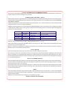
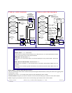
13PINCONNECTOR
RED FUSED WIRE - ( VOLTAGE SENSING ) : + 12 VDC CONSTANT BATTERY SOURCE
This wirecontrols thesensitivity ofthevoltage sensingcircuit, whichdetects theturning onof aninterior lightwhen adoor isopened.
Itwillalsodetectthe switchingon ofparking orheadlamps,andinmanycaseswilltriggerthealarmwhena thermostaticallycontrolled
electronic coolingfanswitches on.
It isrecommended that wheninstalling this systeminto vehicleswith electronic "after fans, " theprocedure for RED FUSED WIRE
- ( HARDWIRE ) should be followed.
Involtage sensingapplications,thecloser tothebatterythatthis wireisconnected,the lesssensitivethevoltage sensecircuitrywillbe.
Moving theconnection point tothe fusepanel willincrease the sensitivityof thevoltage sensing circuitry.
RED FUSED WIRE - ( HARDWIRE ) : + 12 VDC CONSTANT BATTERY SOURCE
When hardwiringthe controlmodule toswitches atall points ofentry, thevoltage sensecircuit mustbe disabled.Move dipswitch # 6
to the " OFF " position. Connect the RED wire toa+12VDCconstant battery source.
WHITE WIRE : + 12 VDC PULSED PARKING LIGHT OUTPUT ( 15 A MAX )
This wireisprovided toflash thevehicle’sparking lights.Connect theWHITEwire tothe positivesideof oneof thevehicle’sparking
lights.
WHITE w/ BLACK TRACE WIRE : POSITIVE OUTPUT TO SIREN OR HORN
This isa3A+12VDCtransistorized switched or pulsed output when triggered ( see Dip Switch #3 ).
In the siren mode, connect this wire to the positive wire of the siren. Secure the black ground wire of the siren to chassis ground.
Inthe hornmode,connect thiswireto terminal85of anexternalrelay,connect terminal86of therelayto ground,anduse thenormally
open and common relay contacts ( 87 and 30 ) to pulse the vehicle’s horn, and move Dip Switch #3 to the "ON" position.
PURPLE WIRE : (+) DOOR TRIGGER
If the vehicle’s door courtesy light switches havea+12VDCoutput when the door is opened ( most Fords ), you must connect this
wiretothepositiveoutputfromoneofthe doorswitches.Donot connectthis wireatthe illuminatedentryoutputfrom thekeylessentry
module. You must connect thiswire at the door ajar switch. In most cases, the PURPLE wire will only need to be connected to one
door switch, no matter how many doors the vehicle has.
IMPORTANT ! Do not use the PURPLE wire if the vehicle has ground output type door switches. (see BROWN wire).
YELLOW WIRE : + 12 VDC IGNITION SOURCE
Connect thiswireto asource thatis+ 12 VDCwhen thekeyis inthe onandcrank positions,and offwhenthe keyis intheoff position.
DARK GREEN w/ WHITE TRACE WIRE : ENTRY ILLUMINATION ( 300 mA MAX. )
The DARK GREEN w/ WHITE TRACE wire provides a 30 second ground signal whenever the system is disarmed using the OEM
transmitter, and pulsesground when thealarm is triggered.
It should be usedto provide the optional entry lighting,and to flash the vehicle’sdome light when the alarm issounding.
Thisisatransistorized,lowcurrentoutput,andshouldonlybeusedtodriveanexternalrelaycoil.ConnecttheDARKGREENw/WHITE
TRACE wiretoterminal 86of anexternalrelay, connectterminal 85ofthe relayto +12VDC battery,and wirethenormally openand
common relaycontacts ( 87 and 30) according tothe polarityof the vehicle’scourtesy light circuit.
DARK BLUE WIRE : MANUAL OVERRIDE INPUT