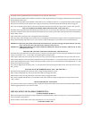
Connect thiswireto theDARKBLUE wirefrom thepush-buttonmanual overrideswitch. ConnecttheBLACK wirefrom theswitch
to chassis ground.
BLACK WIRE : CHASSIS GROUND
Connect this wireto a solid, metal partof the vehicle’s chassis.
ORANGE WIRE : 300 mA GROUND OUTPUT WHEN ARMED
Thiswireisprovidedtocontrolthestartercutrelay.ConnecttheORANGEwiretoterminal86oftherelay,andwiretheremainingrelay
contacts as shown in thewiring diagram.
WARNING !Audiovox does notrecommend using thisrelay to interruptthe ignition wire.Only connect thisrelay to thelow
current solenoid feed wire, as indicated on the wiring diagram.
BROWN WIRE : (-) DOOR TRIGGER
Ifthevehicle’sdoorcourtesylightswitches havea-groundoutputwhen thedooris opened( mostGMand Imports)you mustconnect
thiswiretothenegativeoutputfrom oneofthe doorswitches.Do notconnectthiswireattheilluminatedentryoutputfromthekeyless
entry module. You must connect this wireat the door ajar switch. In mostcases, the BROWN wire will only need to be connected
to one door switch, no matter how many doors the vehicle has.
IMPORTANT ! Do not use the BROWN wire if the vehicle has + 12 Volt output type door switches ( see PURPLE wire ).
LIGHT GREEN WIRE : (-) INSTANT TRIGGER ZONE 1
Thisisaninstant ongroundtriggerwire.Thiswire(zone) shouldbe reservedforconnectiontooptionalgroundoutputtriggerdevices
such as motion and/or shock impact sensors.
DARK GREEN WIRE : (-) INSTANT TRIGGER ZONE 2
This is an instant on ground triggerwire. It must be connected to the previously installed hoodand trunk pin switches.
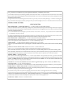
4PINCONNECTOR
IMPORTANT ! When installing the APS-30as a stand alone passive security system, theRED wire in this connector must be
connected toa+12VDCswitched ignition source. RED w/BLACK and GREEN wires must be connected to
ground. The BLUE wire in this connector will not be required for the stand alone installation.
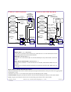
WIRING THE ARM / DISARM INPUTS IN VEHICLES WITH REMOTE 2 STEP UNLOCK
Thefollowing representsthemostcommon wiringroutineinvehicles usingtheremote 2stepunlockfeature.
Dip switches #2 & #5 must be switched to the OFF position in these cases.
GREEN WIRE : ARM INPUT
Connectthiswire tothedriver'sdoorlockmotorwire, whichwillreceive+12voltswhenthe doorsarelocked
using thedoor panel switchor the remotetransmitter.
RED WIRE : DISARM INPUT #1
Connectthiswiretothedriver'sdoorunlockmotorwire,whichwillreceive+12voltswhenalldoorsareunlocked
using thedoor panel switchor the remotetransmitter.
RED w/BLACK TRACE WIRE : DISARM INPUT #2
Connect this wireto any passenger doorunlock motor wire,which will receive +12volts when all doorsare
unlocked using thedoor panel switch orthe remote transmitter,but will not receivethe +12 volt pulsewhen
only the driver'sdoor is unlocked usingthe remote transmitter.


