


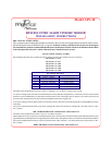


SCENARIO A
SCENARIO B
SCENARIO C
SCENARIO D
RESULT
APS-30 DISARMS
NO CHANGE IN ALARM
STATUS
APS-30 DISARMS
NO CHANGE IN ALARM
STATUS
DISARM #2
RED / BLACK
WIRE
NEGATIVE
POSITIVE
POSITIVE
NEGATIVE
DISARM #1
RED WIRE
POSITIVE
POSITIVE
NEGATIVE
NEGATIVE
VALET AND EMERGENCY OVERRIDE SWITCHES
This systemprovides individual inputsfor two switches,a valet switchand a manualoverride switch. Moving thesetwo functions to
separate switchesprovides an evenhigher level ofsecurity.
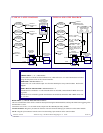
UNDERSTANDING DISARM #1 AND #2:
BecauseofthecomplexitiesofthedifferentfactoryRemoteKeylessEntryUnitsonthemarkettoday,theAPS-30uses(2)disarminputs.
Inallinstallations,whetherinstallingwitha2stepunlockcircuit,singlestepunlockcircuit,orastandalonepassivealarm,bothofthese
wires must be connected.
The followinglogicchart willhelp todemonstrate howthese disarminputs work. As shownin thechart,the APS-30will disarmonly
when Disarm inputs #1 and #2 are at opposing polarities.
Inaddition,whenDipSwitch#2issettotheONposition(1WIREDISARM),thealarmwillnotdisarmwhileitistriggered. Invehicles
withthe singlestepunlock circuits,itis alwaysbesttoset DipSwitch#2 totheOFF position(2wiredisarm), andwireaccording tothe
Audiovox Tech Tips #22 and #23.
A smallredL.E.D. isincluded thatwill serveasa visualindicator ofthe alarmstatus.It shouldbe installedinto thedashboard,located
where it iseasily seen fromoutside the vehicle,yet not distractingto the driver.
Oncea locationhasbeenselected, checkbehindthepanelfor wireroutingaccess,and toconfirmthedrill willnotdamageany existing
components as it passes throughthe panel.
Drill a 1/4" diameter hole,and pass thered and bluewires from theL.E.D. through thehole, from thefront of thepanel. Firmly press
the body ofthe L.E.D. into thehole until fully seated.
VALET SWITCH
Select amounting locationfor thevalet switch, thatis easilyaccessible tothe driverof the vehicle.
The switchdoes nothave tobe concealedsince itwill inno waydisarm thesystem fromthe armedor triggeredstate. The valetswitch
may bemountedbelow oron thedashboardby drillinga 9/32"diameter holein theselectedlocation. Beforedrilling, besureto check
theareabehind thepanelforadequateclearanceforthebody oftheswitch,andtobesure thatthedrillwillnotdamageanycomponents
as it passes through the panel.
MANUAL OVERRIDE SWITCH
Selectamountinglocationforthemanualoverrideswitch,thatisconcealed,anddoesnotnecessarilyhavetobewithinreachofthedriver.
Asecurelocationisinthetrunkofthevehicle,sincepressingthisswitchwillactivateatimer,whichwillthengivethedriver12seconds
to turn the ignition key to the " ON " position.
Themanual overrideswitchmay bemountedby drillinga1/4 "diameterholein theselectedlocation. Beforedrilling,be suretocheck
theareabehind thepanelforadequateclearanceforthebody oftheswitch,andtobesure thatthedrillwillnotdamageanycomponents
as it passes through the panel.
SIREN
Selecta mountinglocationinthe enginecompartmentthatis wellprotectedfromaccess belowthevehicle. Avoid areasnearhighheat
components or moving parts withinthe engine compartment. To prevent water retention, the flared endof the siren must be pointed
downward when mounted.
Mount the sirento the selected locationusing the screws andbracket provided.
HOOD AND TRUNK PIN SWITCHES