


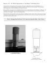

2. Using a 1/8” allen wrench, loosen the two (2) set screws located at the top and side of the
front plate. Gently slide the array detector mounting flange all the way out of the
SP-500i housing. Make sure that the sliding tube and o-ring are kept clean.
3. Remove the shipping cover from the sliding tube, and the spacer if not required.
4. Position the array detector mounting flange against the array detector, and match the hole
patterns. When correctly positioned, the baffle aperture orientation should match the
detector array orientation. If it does not align properly, contact Princeton Instruments.
5. Fasten the array detector mounting flange to the detector, then carefully slide this assembly
back into the SP-500i housing.
6. Tighten the #10-32 set screw on the top of the front plate first, and then tighten the one on
the side.
7