


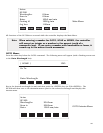

INIT-GRATING Selects which of the three gratings on the installed turret the monochromator will go to
after finding 0.0 nm on the first grating of the installed turret.
E.G. 2 INIT-GRATING selects the second grating as the default. Accepts values 1 - 9.
INIT-WAVELENGTH Sets an initial wavelength for the monochromator after initialization.
E.G. 435.84 INIT-WAVELENGTH
INIT-SRATE Sets an initial scan rate for the monochromator.
E.G. 500.0 INIT-SRATE
Section IV-D: Focusing and Alignment of Array Detectors
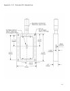
With the array detector properly mounted to the SP-500i, use the following procedure to align and
focus the array detector to the SP-500i optical system. It is assumed that the array detection
system is running for the following procedure.
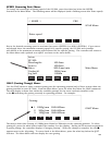
1. Mount a light source such as a mercury pen-ray type to the entrance slit of the
SP-500i. Princeton Instruments offers a standard mercury lamp, Model MS-416, designed
for this purpose. Any light source with line output can be used. If there are no “line” sources
available, it is possible to use a broad band source such as tungsten for the alignment. If
this is the case, use only a wavelength setting of 0.0nm for alignment purposes.
2. With the SP-500i properly connected to the controller or computer, turn the power ON and
move the spectrograph to a wavelength of 435.8 nm if using a mercury lamp, or 0.0 nm for a
broad band source, or another wavelength corresponding to a spectrum produced by another
“line” source.
3. With the array detector operating, check the image of the light source if running in an
imaging mode with a CCD. Otherwise check the line intensity and shape.
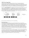
4. Using a 1/8” allen wrench, loosen the two (2) #10-32 set screws (approximately 2 turns)
located on the top and side of the front plate, and slowly slide the array detector IN or OUT
until the sharpest image is achieved, or the sharpest line is achieved.
5. Move the thumb wheel until it just makes contact with the array detector mounting flange.
This enables you to rotate the detector without changing the focus position. Rotate the
detector for correct alignment. The thumb wheel adjustments may be used to precisely
position the detector - one eighth of a turn of the thumb wheel changes the detector position
by approximately 1/10th of a millimeter.
6. After each adjustment, ensure the array detector mounting flange is in contact with the
thumb wheel and the two (2) push screws. Tighten the #10-32 set screw on the top of the
front plate first, and then tighten the one on the side to secure the detector.
7. Best spectral resolution is obtained when the array detector is aligned to the SP-500i.
The light source can be removed if desired, and replaced by fiber optics or other light sources.
8. If fibers or other imaging optics are used to bring light into the SP-500i, they may
require adjustment along the optical axis to achieve best vertical image quality.
19
CAUTION:
The set screws must be loose when turning the thumb wheel
adjustment, or severe damage will occur. The distance between the
edge of the array detector mounting flange and the instrument MUST
NOT exceed .33”.