


III. SP-500i Setup
Section III-A: Unpacking and Inspection
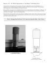
Carefully unpack and examine the SP-500i and any accessories purchased.
Section III-B: Connecting the SP-500i Monochromator/Spectrograph to the
Optional Model 500-749 Remote Scan Controller or Computer
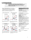
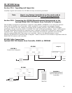
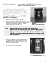
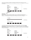
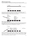
The SP-500i is designed for operation by computer using RS232 or IEEE488, or by using the optional
Model 500-749 Remote Scan Controller. Either method of control enables wavelength scanning
at a pre-set linear scan rate, change of scanning speeds, grating selection, rapid GOTO wavelength
positioning, change of grating turrets if available, and “jog” wavelength positioning. Figure 1 below shows
the cable connections necessary for operation from a computer through the COM ports or with a GPIB
controller card. Figure 2 below shows the cable connections necessary for operation of the SP-500i
with the optional Model 500-749 remote scan controller. Refer to the Monochromator Control
Software for Windows for operation with a computer. Refer to Section IV-B for details on operation with the
Model 500-749 remote scan controller.
SP-500i Cable Connections:
Optional 500-749 Remote Scan Controller, RS232, or IEEE488
4
Note: Report any damage immediately to the carrier and to
Princeton Instruments and save all packing material.
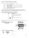
power
RS232
GPIB
POWER
SUPPLY
GPIB Controller
COM Port*
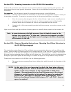
power
RS232
GPIB
POWER
SUPPLY
FIGURE 1
Control from Computer
FIGURE 2
Control from Optional
500-749 Remote Scan
Controller
*COM 1
or
COM 2
SP-500i Computer
SP-500i
500-749