


Section III-D: Mounting Accessories to the SP-500i Slit Assemblies
All Acton SP accessories come with their own set of instructions for proper mounting and operation. The
instructions below are only general information. Please refer to the individual instructions for detailed
information.
Accessories: The full range of Acton SP accessories mount directly to the SP-500i slit
assemblies. A drawing of the standard slit assemblies can be found in the Appendices Section to assist you
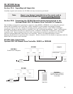
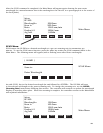
in mounting accessories. To mount an accessory to the slit, the general procedure is as follows:
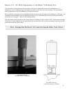
1. Place the accessory directly against the face of the slit body. Light sources normally mount
on the entrance slit, detectors on the exit slit. Other accessories such as fiber bundles
normally mount on the entrance slit, but are also compatible with the exit slit.
2. Using four (4) 8-32 screws normally provided with the accessory, secure the accessory to the
slit body.
Light sources fitted with light collection/focusing optics are normally factory aligned to the standard slit.
Section III-E: Detector Mounting Instructions: Mounting Focal Plane Detectors to
the SP-500i Spectrograph
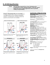
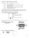
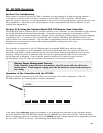
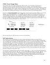
The standard mounting flange for CCDs and diode arrays accommodates detectors with two different bolt
circles. There are three (3) equally spaced #10-32 tapped holes on a 3.60” bolt circle, and three (3) equally
spaced holes on a 3.88” bolt circle designed to accept #10-32 button head screws. A baffle is mounted in
the array detector mounting flange to define the focal plane area. This baffle has two sets of mounting holes
90 degrees apart which permit the mounting to be rotated 90 degrees to accept different array detectors.
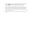
To mount an array detector to the SP-500i, use the following procedure:
1. The array detector mounting flange has a sliding tube, which fits inside the front plate of the
SP-500i.
6
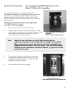
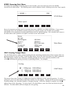
Note: In some instances with light sources, there is limited access to the
bottom two screw holes. In this case, Princeton Instruments provides
special slotted holes in the light source housing to facilitate mounting
of the source to the slit.
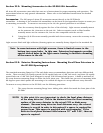
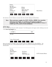
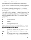
NOTE: At this point it is very important to check the focal plane distance
of the array detector. This is the distance from the front mounting
surface of the array detector to the actual CCD or diode array
element. Because array detector focal distances vary, the correct
distance is crucial in order to determine if a spacer is required for
proper focus. This spacer is provided with spectrographs. If the
detector focal plane distance falls between .67” and 1.00”, then no
spacer is required.