


Rev. K, p. 6 of 11
6. TIGHTEN ALL BOLTS
6.1 Tighten all
cab bolts at this time. Reminder: do not
over-tighten the six (6) self-tapping floorboard screws.
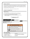
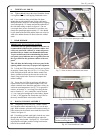
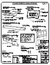
6.2 Use a small bar clamp to hold the side frame
against the top side tubular frame. Using a drill and a
Phillips head bit, install two self-drilling and self-tapping
screws through the “P” clamps and into the underside of
the side frame tubing as shown in figure 6.2. Do not
over-torque these screws. Reminder: be sure these two
clamps are spread apart approximately 13”. One should
be just ahead of the ball stud and the other one as far for-
ward as the tubular frame will allow before the welded
seam.
7. REAR WINDOW
IMPORTANT INSTALLATION NOTICE!
To facilitate the rear panel installation to the cab, it is
recommended to lubricate the perimeter rubber seal
of the rear panel with a silicone or Armor All protec-
tant/lubricant (or similar) non-flammable lubricant.
To prevent lubricant from contaminating the plastic
rear panel, spray lubricant onto a rag and in turn use
the rag to lubricate the perimeter rubber of the rear
panel.
This will allow the full seating of the rear panel in the
opening which is necessary for proper hole alignment.
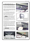
7.1 Lift the bed. With assistance, place the rear window
in position. Fasten using four 1/4-20 x 1 1/4” long Truss
head, Phillips head bolts and four fender washers into
factory installed weld nuts on the rear tabs on the side
frames. Snug up the bolts. Do not over-compress the
rubber bushings.
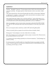
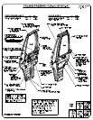
7.2 Secure the vinyl filler by applying self-adhesive
backed velcro to the vehicle where needed. Note: self-
adhesive backed velcro should be applied to a clean, dry
surface at room temperature. See fig. 7.2 for general lo-
cations. At location “a”, use a long piece along the bot-
tom; at location “b”, use a small piece; and at location
“c”, use a long piece straight up to rear window. Repeat
“b” and “c” for opposite side. Attach the vinyl filler to
the newly installed hook velcro on the vehicle.
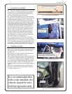
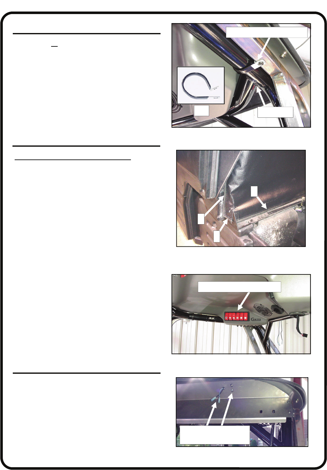
8. ROOF & CONSOLE ASSEMBLY
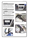
8.1 Temporarily remove and save 2 fender washers
and 2 locknuts where indicated in fig. 8.6.1 on the next
page. With assistance, place the roof/console assembly in
place oriented so the controls are towards the front of the
vehicle. See figure 8.1.
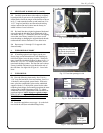
8.2 If installing optional work lights, feed the two wires
through the hole in the windshield support where the
Heyco plugs were located. See figure 8.2. If not install-
ing optional work lights, push the wiring back into the
holes of the overhead console.
Fig. 8.1 View from passenger’s side
controls to be towards the front
Fig. 6.2 View from passenger’s side
Ref.
flat portion towards the ground
welded joint
Fig. 7.2 View of driver’s side lower rear corner
Fig. 8.2 View from driver’s side
Ref.: work light wires and
bracket mounting holes
b
a
c