


Rev. K, p. 5 of 11
3. SIDE FRAME & DOOR ASS’Y. (cont’d.)
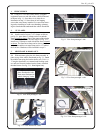
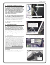
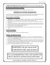
3.2 Carefully open the door to the midway or slightly
beyond position to gain access for installing the hip re-
straint bracket. Insert the tongue of the bracket as shown
in fig. 3.2 and rotate the bracket up and install one 5/16-
18 x 1” long hex head bolt, one internal tooth locking
washer, and one flat steel washer into the factory in-
stalled weld nut. Leave bolt loose.
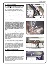
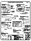
3.3 Re-install the three original equipment floorboard
screws through the bolt holes in the floorboard of the
side frame. See fig. 3.3. Reminder: these are self-tapping
screws that were factory installed. Use care to avoid
cross-threading or damaging the original female threads
underneath the vehicle floorboard. Leave bolts loose.
3.4 Repeat steps 3.1 through 3.3 for opposite side
frame assembly.
4. WINDSHIELD SUPPORT
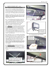
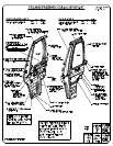
4.1 If installing optional work lights, pop the two
Heyco plugs out and discard them. If not installing op-
tional work lights, leave the plugs in place. With assis-
tance, install the windshield support as shown in fig. 4.1.
Install four 5/16-18 x 3/4” long hex head bolts, four in-
ternal tooth locking washers, and four flat steel washers.
Factory installed weld nuts are provided on the tabs of
the side frame. See right side of figure 4.1. Leave bolts
loose.
5. WINDSHIELD
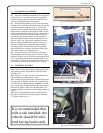
5.1 Have the following items ready: four 5/16-18 x
1 3/4” long flat head bolts, four steel washers, four 5/16-
18 locknuts, and two plastic spacer blocks. With assis-
tance, place the windshield in place on the windshield
support with the 3/4” thick plastic spacer blocks under-
neath the plastic hinges for mounting up against the outer
surface of the windshield support per fig. 5.1. Adjust
windshield seal to the vehicle hood with side latches en-
gaged and tighten. NOTE: hinges are plastic compo-
nents. Do not overtighten. Torque to 7 ft.-lbs. max..
WARNING: do not travel with windshield in full
open position.
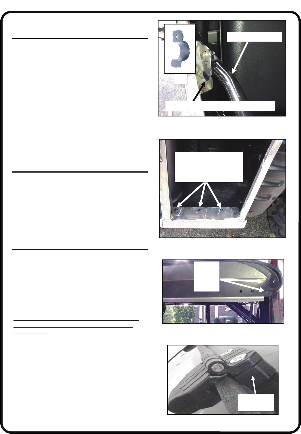
5.2 Install the supplied nut covers (qty.: 4) on the lock-
nuts inside the cab (front windshield hinge bolts).
Fig. 4.1 View from driver’s side
side
frame
mounting
holes
Fig. 5.1 View from driver’s side
3/4” thick
plastic spacer
Fig. 3.3 View from passenger’s side
re-install 3 bolts per side
using care to avoid damag-
ing female threads under-
neath vehicle floorboard
Fig. 3.2 View from passenger’s side
Ref.
Ref.: hip restraint tube
bent tab without hole slides into receiving slot