


Rev. K, p. 4 of 11
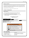
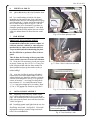
1. VEHICLE PREP.
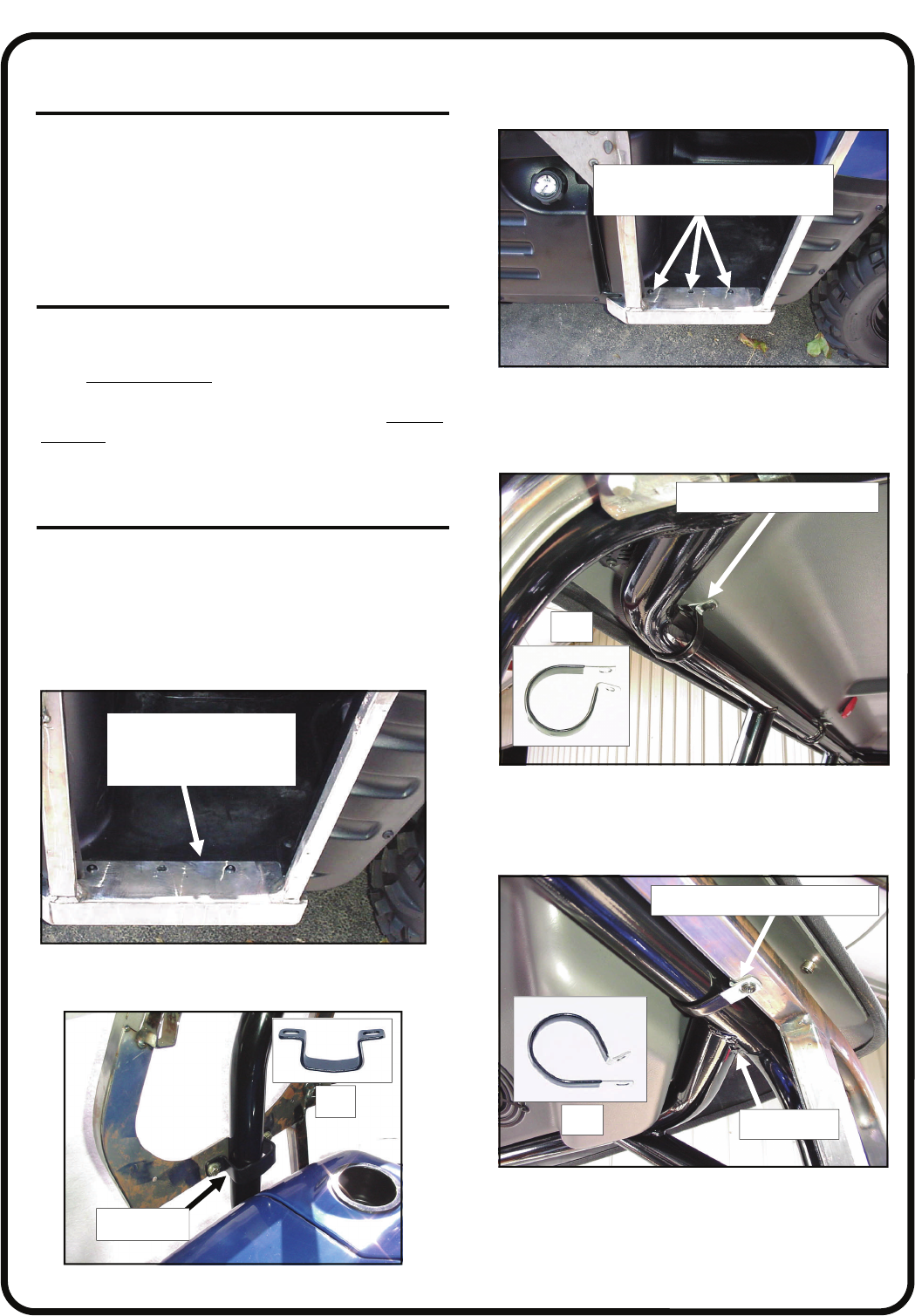
1.1 Using a T27 Torx bit, remove three (3) original
equipment screws on each side of the vehicle floorboard
as shown in fig. 1.1. Save these six (6) bolts for re-
installation in step 3.3. Note: these are self-tapping
screws that were factory installed. Use care when remov-
ing and re-installing to avoid cross-threading or damag-
ing the female threads underneath the vehicle floorboard.
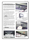
2. “P” CLAMPS
2.1 Install a total of seven (7) “P” clamps as follows:
per fig. 2.1, place three (3) clamps on the rear tubular
frame oriented as shown
. One in the center of the tubular
frame and one per side on the outer edges. Per fig. 2.1.1,
install two (2) clamps on each side tubular frame oriented
as shown. The front most clamp can be close to the front
welded joint and the rear most clamp can be 13” behind
the front one. Hardware will be installed in step 6.2.
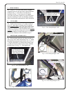
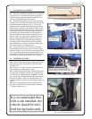
3. SIDE FRAME & DOOR ASS’Y.
3.1 With assistance, place the side frame assembly in
place on top of the vehicle floorboard per fig. 3.1. Attach
the middle front using the bracket shown, two 5/16-18 x
1” long hex head bolts, two internal tooth locking wash-
ers, and two flat steel washers into the factory installed
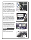
threaded inserts. See fig. 3.1.1. Hand tighten only.
Fig. 1.1 View from passenger’s side
Fig. 3.1 View from passenger’s side
place floorboard of side
frame onto floorboard of
vehicle lining up 3 holes
Fig. 3.1.1 View from driver’s side
Ref
front clamp
Fig. 2.1 View from passenger’s side
Ref.
Fig. 2.1.1 View from passenger’s side
Ref.
welded joint
flat portion towards the ground
flat portion towards the sky
remove and save 3 bolts per side
before installing side frame