


Pharos Drive GPS 140 9 Chapter 2 Getting Started
Pharos
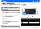
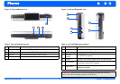
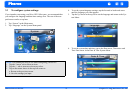
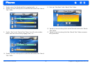
Figure 2: Top and Bottom view Figure 3: Left and Right side view
Table 3: Top and Bottom controls
No. Function
1 Power button Normal On/Off power button.
2 USB input Connects to the USB cable.
3 On/Off The main power/battery cutoff switch.
4 Reset Restarts your device with a soft reset.
1
2
3 4
Table 4: Left and Right panel controls
No. Function
1 Headphone Standard stereo headphone jack.
2 DC Power input For Adapter or car charger
3
FM/TMC
antenna
For FM/TMC reception
4 SD slot Accepts a SD (Secure Digital) card for data storage.
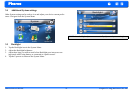
5GPS antenna
This connector (under rubber dust cover) allows use of
an optional external GPS antenna.
6 Light sensor
Automatically adjust Backlight to light conditions
(nighttime/daytime).
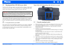
WARNING: Make sure the SD card is properly inserted and DO NOT
remove the SD card during operation of the device.
1
2
4
3
5
6