


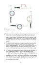

Set Point Adjustment (Relay Output Only)
1) Adjust the flow rate through the line in which the flow sensor is
installed to the rate that corresponds to the desired relay trip point.
2) If the red LED on the back side of the sensor is not illuminated, use a
small flat bladed screwdriver to slowly turn the adjustment screw on the
set point potentiometer counter-clockwise until the red LED illuminates.
3) If the red LED is already illuminated, turn the adjustment screw on
the potentiometer clockwise until red LED turns off. Next, slowly
rotate the adjustment screw counter-clockwise until the red LED
illuminates.
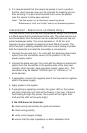
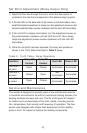
4) Once the set point has been adjusted, the relay will operate as
shown in the Truth Table illustrated in Table 2 below.
Table 2.: Truth Table - Relay Operation
Service and Maintenance
The sensor is designed to provide years of low maintenance service
in industrial environments. As with all mechanical rotating devices, the
bearing surfaces will wear with use. The life of the parts will depend
on factors such as cleanliness of the fluid, media, mounting orienta-
tion, temperature, fluid velocity and frequency of operation. The flow
sensor was designed with simple field-replacement of the rotating
parts in mind. To inspect or replace the rotating components:
(9)
Condition
Relay NC
Contact
Relay NO
Contact
Red LED Green LED
Flow rate<
set point
Open Closed Illuminated Illuminated
Flow rate >
set point
Closed Open
Not
Illuminated
Illuminated
Loss of power
to sensor
Open Closed
Not
Illuminated
Not
Illuminated