


Installation - Electronic (Relay Output Only)
1. Connect the red wire from the sensor to the positive terminal of the
12-35 V
DC power supply.
2. Connect the black wire from the transmitter to the negative terminal
of the 12-35 V
DC power supply.
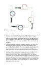
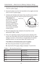
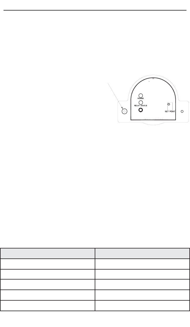
3. (Versions with stainless steel sensor body only) Be sure to properly
ground the flow sensor by using the ground screw shown
in Illustration 2 to
connect the sensor body
Earth ground. This step
may be unnecessary if
the piping system that the
flow sensor is plumbed
into is already connected
to Earth ground.
4. Wire the appropriate relay contacts to the load that is to be
switched per Table 1 below.
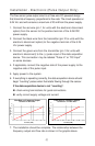
5. If the unit is operating correctly, the green power indication LED
and the red relay status LED should illuminate after the DC supply
voltage is turned on. As fluid flow is increased above the factory-
adjusted set point, the red relay status LED should turn off.
If the LEDs do not illuminate when power is applied:
check wiring terminations for good connections
verify that the DC supply voltage is between 12 and 35 V
DC
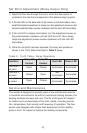
Table 1.: Wiring Connections
(8)
Wire Color Connection
Red +12-35 VDC
Black DC Ground
Green Relay Common
White Relay Normally Closed Contact
Brown Relay Normally Open Contact
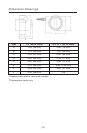
Illustration 2
GROUND SCREW