


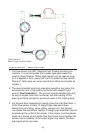

4. It is recommended that the sensor be placed in such a position
that the round access cover can be removed for cleaning and tur-
bine servicing. It is also recommended that a union be placed
near the sensor to allow easy removal.
Note1: The flow sensor is a bi-directional measuring device.
References to “inlet” and “outlet” refer to uni-directional systems.
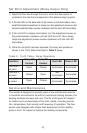
Installation - Electronic (4-20mA Only)
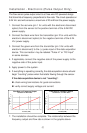
The flow sensor circuit is a two-wire loop-powered design that transmits
a 4-20mA signal that is proportional to flow rate. The noise-immune cur-
rent transmission from the sensor can be routed with low cost two con-
ductor twisted-pair cable. The circuit operates on 12-35 VDC and
requires a source capable of supplying at least 20mA of current. The
circuit has built in polarity protection and over-current limiting to protect
both the transmitter and what the transmitter is connected to.
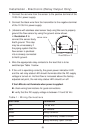
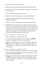
1. Connect the red wire (pin 1 for units with the electronic disconnect
option) from the transmitter sensor to the positive 12-35 V
DC
power supply output.
2. Connect the black wire (pin 2 for units with the electronic disconnect
option) from the transmitter to the positive side of the loop load
(resistor, chart recorder, data acquisition board, meter, etc.). This
connection may be labeled "4-20mA Input" or "4-20mA (+)" on
some devices.
3. If applicable, connect the negative side of the loop load to negative
side of the power supply.
4. Apply power to the system.
5. If everything is operating correctly, the green LED on the sensor
will dimly illuminate and 4mA will be flowing in the loop. If there is
fluid flowing through the sensor, the current will be higher than
4mA and the LED will be quite bright.
If the LED does not illuminate:
check wiring terminations for good connections
check wiring polarity
verify correct supply voltage
ensure that the load impedance is within allowable limits
(5)