


Installation - Electronic (Pulse Output Only)
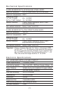
The flow sensor pulse output circuit is a three-wire DC-powered design
that transmits a frequency proportional to flow rate. The circuit operates on
5-24 V
DC and will consume a maximum of 25 mA from the power supply.
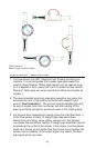
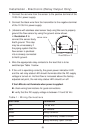
1. Connect the red wire (pin 1 for units with the electronic disconnect
option) from the sensor to the positive terminal of the 5-24VDC
power supply.
2. Connect the black wire from the transmitter (pin 2 for units with the
electronic disconnect option) to the negative terminal of the 5-24
V
DC power supply.
3. Connect the green wire from the transmitter (pin 3 for units with
electronic disconnect) to the (+) pulse input of the data acquisition
device. This connection may be labeled "Pulse In" or "DC Input"
on some devices.
4. If applicable, connect the negative side of the power supply to the
negative side of the pulse input.
5. Apply power to the system.
6. If everything is operating correctly, the data acquisition device should
begin "counting" pulses when fluid starts flowing through the sensor.
If the data acquisition device is not “counting”:
check wiring terminations for good connections
verify correct supply voltage and current
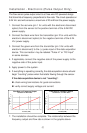
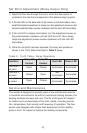
7. The installation should be complete. The relationship between the
frequency output and flow rate is shown in the graphs above.
(7)
Flow Rate vs. Fre
q
uenc
y
Out
p
ut
Standard 1/2" NPTF Units
0
10
20
30
40
50
60
0246810121416
Flow Rate (GPM)
Frequency (Hz)
Flow Rate vs. Fre
q
uenc
y
Out
p
ut
Standard 3/4" & 1" NPTF Units
0
10
20
30
40
50
60
0102030405060
Flow Rate (GPM)
Frequency (Hz)