


Apply the DC supply voltage directly across the sensor wires. If
the LED does illuminate, the load is either: too great of imped-
ance or an open circuit. If the LED does not illuminate, the sen-
sor's lead wires or circuit are defective.
6. The installation should be complete.
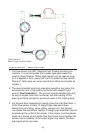
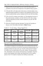
Installation - Electronic (0-5VDC Output Only)
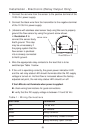
1. Connect the red wire (pin 1 for units with the electronic disconnect
option) from the sensor to the positive terminal of the 12-35 VDC
power supply.
2. Connect the black wire from the transmitter (pin 2 for units with the
electronic disconnect option) to the negative terminal of the 12-35
VDC power supply.
3. Connect the green wire from the transmitter (pin 3 for units with
electronic disconnect) to the (+) 0-5 V
DC input of the data acquisi-
tion device. This connection may be labeled "Voltage Input" or
"Analog Input" on some devices.
4. If applicable, connect the negative side of the power supply to the
negative side of the pulse input.
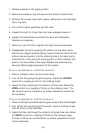
5. Apply power to the system.
6. If everything is operating correctly, the green LED will illuminate
brightly and the data acquisition device should show an increase in
flow rate as fluid starts flowing through the sensor.
If data acquisition device does not show an increase in flow rate:
check wiring terminations for good connections
verify that the LED is illuminated
verify that the DC supply voltage is between 12 and 35 V
DC
(6)