Appendix B – DL Specifications
DL™ User Manual Rev 3 39
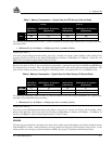
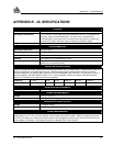
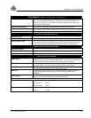
PERFORMANCE (Subject To GPS System Characteristics)
RT-2
Pseudorange & carrier-phase double differencing (fixed < 2 cm RMS accuracies
with RTK carrier-phase positioning). Conditions: <10 km baseline length; ≥ 6
satellites at an elevation > 12°; after 2 minutes convergence; with choke-ring
ground plane at base station.
Time Accuracy (relative)
250 ns (SA on) – does not include delays due to cable on RF section
Height Limit
Up to 18,288 m (60,000 feet), in accordance with export licensing
Velocity Limit
Up to 515 m/s (1000 Nmi/hr), in accordance with export licensing
RF INPUT / LNA POWER OUTPUT
Connector on DL
Standard 50 Ω TNC female type
RF Input
1575.42 MHz, 1227.60 MHz
Power Output to LNA
4.25 - 5.25 V DC @ 0 - 90 mA. Note: if the antenna draws current above this
limit, power to the antenna is disabled and the antenna self-test status flag is set
to zero. Refer to the documentation for the RVSA log for more information.
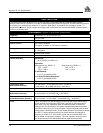
INPUT/OUTPUT DATA INTERFACE
Dual RS-232C Serial
Bit rates: 300, 1200, 4800, 9600, 19200, 57600, 115200 bps (9600 bps default)
Signals supported
TX, RX, RTS, CTS, DTR, DSR, DCD
Electrical format
EIA RS232C Standard
INPUT/OUTPUT STROBES
VARF Output
A programmable variable frequency output ranging from 0 - 5 MHz (refer to
FREQUENCY_OUT command), with pulse width = 1 ms. This is a normally high,
active low pulse. There may be as much as 50 ns jitter on this signal.
PPS Output
A one-pulse-per-second time synchronization output. This is a normally high,
active low pulse (1 ms ± 50 ns) where the falling edge is the reference.
Measure Output
4 pulses-per-second output, normally high, active low where the pulse width is 1
ms. The falling edge is the receiver measurement strobe.
Mark Input
An input mark (negative pulse > 55 ns), time tags output log data to the time of
the falling edge of the mark input pulse (refer to LOG command syntax –
ONMARK).
Status Output
Indicates a valid GPS position solution is available. A high level indicates a valid
solution or that the FIX POSITION command has been set.
The electrical specifications of the strobe signals are as follows:
Output
Voltage: Standard TTL levels
Sink Current:
Source Current:
64 mA
15 mA
Input
Voltage: Standard TTL levels
Current: ≤ 5 mA


