2 – Set Up
22 DL™ User Manual Rev 3
NOTE: The coaxial cable should be connected to the antenna and DL before power is supplied. If the antenna cable
becomes disconnected from the antenna or DL, turn the DL off before reconnecting the cable; this prevents the DL’s
antenna current-limiting circuit from unnecessarily activating.
Coaxial cables should be handled with care. They should not be routed over surfaces where they could be stepped on,
pinched, or cut. A cable that has been stretched, has nicks in its outer jacket, or has crimps resulting from being bent too
tightly, generally has higher losses than otherwise.
While there may be other coaxial cables on the market that might also serve the purpose, please note that the performance
specifications of the DL are guaranteed only when it is used with NovAtel-supplied RF cables.
POWER PORT & CABLE
The DL requires an input supply voltage that can come from batteries, a wall outlet adapter (AC/DC converter), or an
automotive power source. The DL has an internal power module that does the following:
• filters and regulates the supply voltage
• protects against over-voltage, over-current, and high-temperature conditions
• provides automatic reset circuit protection
WARNING: Supplying the DL with an input voltage that is below +10.7 will cause the unit to suspend operation.
An input voltage above +18 V DC may physically damage the unit.
The 4-pin power connector allows power to be supplied from two independent sources, although only one is used at a
time. If two power sources are available, the DL monitors their supply voltages independently, and on power-up, chooses
the one with the higher voltage. If the current power source becomes unusable, the DL then switches to the second one
(if available) without any interruption in its logging activities.
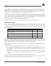
Consider the case where the DL is connected to two 12 V DC batteries. As described in Table 4, Page 26, as the voltage
drops on the first battery, the Power indicator color changes from green to amber, then to red. Warning messages are sent
on the serial port indicating that battery power is becoming exhausted (see the description of the LPSTATUSA log, Page
73 and MSGA log, Page 75 if you require further information). Then, the DL switches to the second battery. Once both
batteries are depleted, the DL shuts itself off. To maximize a battery’s lifetime, the DL does not use it once it is
discharged.
As is also described in Table 4: Status Indicators - Meaning, Page 26, when the DL is connected to two batteries, the
Power indicator is pulsed (in the appropriate color) to distinguish between battery A and battery B. One long “blink”
corresponds to battery A, and two short blinks in rapid succession correspond to battery B. Only the status of the active
battery is indicated.
The data logging mechanism is designed to be robust and to endure power interruptions (and similar disruptive events)
with minimum loss of data. In these situations, less than 5 minutes of data (prior to the disruptive event) are lost. To the
extent possible, error messages attempt to describe the problem. If you require further information on this topic, see the
description of MSGA log, Page 75.
As shown in Figure 10: Power Cables, Appendix D, Page 41 there may be up to four power cables used with the DL.
These cables allow you to energize the DL by either an AC source or a DC source:
• 4-pin LEMO plug connector to cigarette-lighter plug, complete with a 3-amp slow-blow fuse
• 4-pin LEMO plug connector to autoranging AC/DC converter/battery charger, and AC power cord
• optional power cable connecting the DL to a battery (33.5 cm or 75 cm lengths)
• optional Y-cable to power the DL from two batteries


