


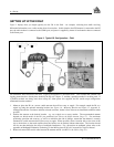
2 – Set Up
20 DL™ User Manual Rev 3
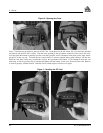
system composed of devices that need to be synchronized with each other. For example, you could connect the DL to an
aerial camera in such a way that the DL recorded its position whenever the shutter button was pressed. This port is not
typically used for stand-alone applications. The five signals are described further in Table 14: I/O Connector Pin
Assignment, Page 45, as well as in the Input / Output Strobes section of Appendix B.
The I/O strobe lines can be accessed by inserting the 8-pin LEMO connector of the I/O strobe port cable into the I/O port.
Figure 13, Page 45, and Table 15: I/O Cable – Pin Assignment, Page 46 contains wiring and pin-out information on this
cable. The other end of the cable is provided without a connector so that you can provide an application-specific one; the
jacket insulation is cut away slightly from the end but the insulation on each wire is intact.
This port incorporates filters to suppress electromagnetic interference.
See Appendix H - Replacement Parts if you need to consult the list of NovAtel and LEMO part numbers.
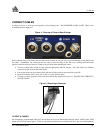
SERIAL PORTS & CABLES
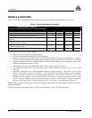
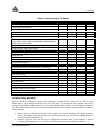
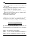
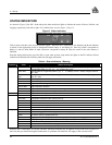
The two serial ports (COM1 and COM2) are bi-directional. There is a multicolor indicator above each of these serial
ports. If it glows red, data is being received on that port, while if it glows green, data is being transmitted on that port. If
it glows yellow, data is being received and transmitted simultaneously on that port. The features present for each serial
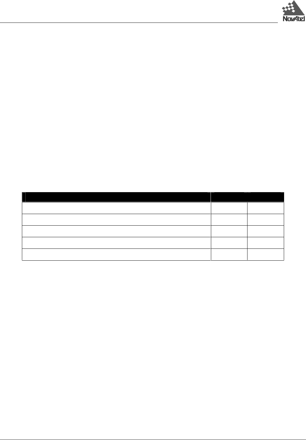
port is listed following:
FEATURES COM1 COM2
300, 1200, 4800, 9600, 19200, 38400, 57600 and 115,200 BPS data rates
√ √
RS-232C signal levels
√ √
Electromagnetic interference suppression filters
√ √
Hardware and Software flow control operation
√ √
BAT voltage output
× √
For communication to occur, the DL serial port configuration must match that of the external device’s. The DL’s default
port settings are [RS232C, 9600 BPS, no parity, 8 data bits, 1 stop bit, no handshaking, and echo off]. Changing the
default settings can be easily accomplished using SoftSurv UTILITIES software module, or by means of the COMn
command (which is described in the MiLLennium GPSCard Command Descriptions Manual).
On either serial port, only the RX, TX, and GND lines need to be used. Handshaking is not required, although it can
optionally be used.
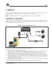
Two serial data cables are supplied to connect the DL to a PC or modem. They are described as follows:
• null-modem cable: 10-pin LEMO plug to 9-pin D-connector (DE9S socket); it is described further in Figure 12 &
Table , Appendix D, Page 44. This is used to connect the DL to a serial (RS232C) communication port on a
terminal or PC.
• straight cable: 10-pin LEMO plug to 9-pin D-connector (DE9P plug); it is described further in Figure 11 & Table
, Appendix D, Page 43. This is used to connect the DL to a modem or radio transmitter to propagate differential
corrections.
The 10-pin plug on each cable can be plugged into either the COM1 or COM2 port on the DL.
For further information on the signals or connector pin-outs for the serial ports or cables, please see the Input / Output
Data Interface section of Appendix B, Page 37, and Table , Page 42, in Appendix D.